&KDSWHU&RQILJXULQJWKH'HYLFH
,QVWDOOHU·V*XLGH
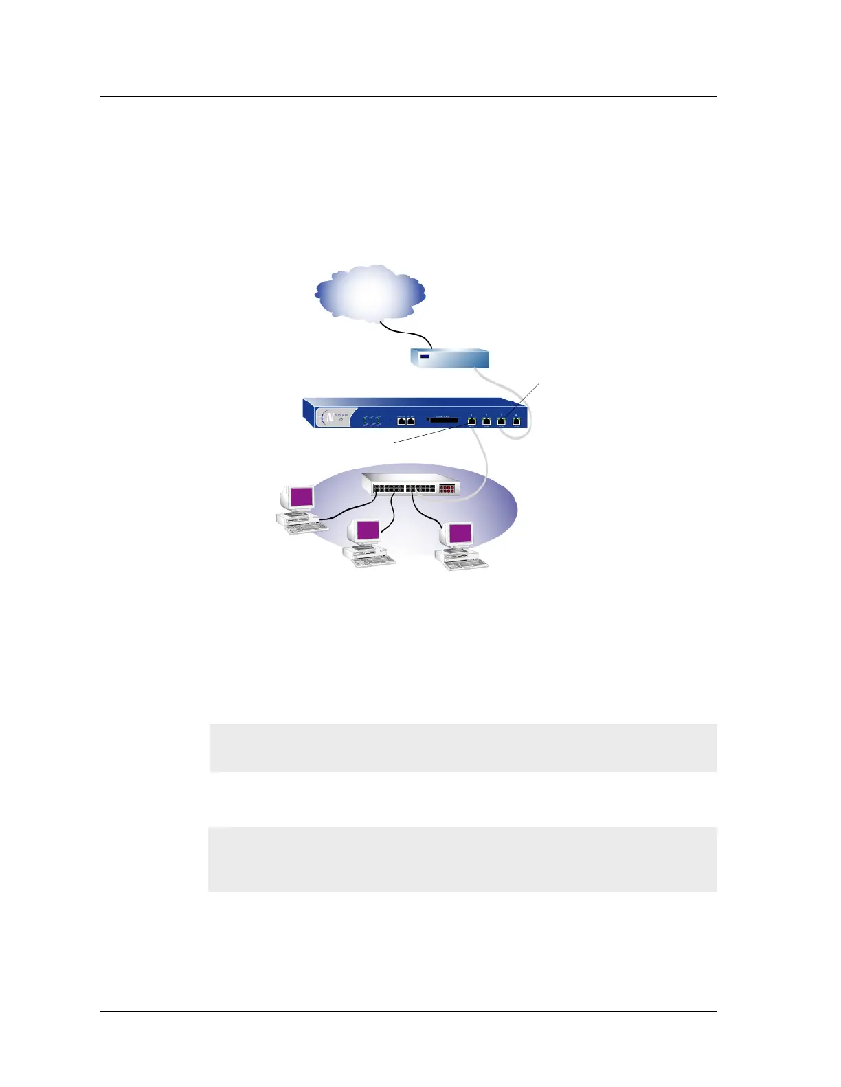
&211(&7,1*7+('(9,&(72$1(7:25.
The following illustration shows typical cabling for 10/100 BaseT networks. This example
uses the default interface bindings for the Ethernet ports.
To add a NetScreen-50 device to your network:
1. (Optional) Install the NetScreen-50 device in an equipment rack (see
“Equipment Rack Mounting” on page 9).
2. Make sure that the power switch on the device is turned OFF.
3. Connect the power cable, included in the product package, to the NetScreen-50
power outlet at the rear of the device and to a power source.
4. Connect an RJ-45 cross-over cable from the Trust zone interface (Ethernet port
1) to the internal switch, router, or hub.
5. Connect an RJ-45 straight-through cable from the Untrust zone interface
(Ethernet port 3) to the external router.
6. Flip the power switch to the ON position.
Warning! To prevent personal injury from exposure to DC voltage, always
replace the insulating cap after installing power cables.
Note: Check your router, hub, switch, or PC documentation to see if these devices
require any further configuration. In addition, see if it is necessary to switch OFF
the power to any new device you add to the LAN.
Internet
Ethernet port 1
Ethernet port 3
Router