(VWDEOLVKLQJDQ+$&RQQHFWLRQ%HWZHHQ'HYLFHV
1HW6FUHHQ
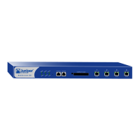
7. After the NetScreen-50 device boots up, check the following LEDs:
– The Power LED glows green.
– The Status LED blinks green.
– The Ethernet port LEDs for each connected interface glows or blinks
green. (For more details about interpreting the Link Status LEDs, see
“Ethernet Interfaces” on page 5.)
(67$%/,6+,1*$1+$&211(&7,21%(7:((1'(9,&(6
To assure continuous traffic flow in the event of system failure, you can cable and
configure two NetScreen devices in a redundant cluster. The devices propagate all
network, configuration and session information to each other. Should one device fail, the
other takes over the traffic processing.
The following diagram shows a typical HA setup for NetScreen-50 devices.
RouterRouter
Layer-3 Switch 2Layer-3 Switch 1
From HA to HA interface
To Untrust interface
From Trust interface
Switch 4
Switch 3
Internet
From Trust interface
Device 1 Device 2
LAN
To Untrust interface