Physical Interface Modules 51
6. If necessary, arrange the cables to prevent them from dislodging or developing
stress points:
Secure the cable so that it is not supporting its own weight as it hangs to
the floor.
Place excess cable out of the way in a neatly coiled loop.
Use fasteners to maintain the shape of cable loops.
7. Loosen and remove the screws on each side of the PIM faceplate using a
1/8-inch flat-tip screwdriver.
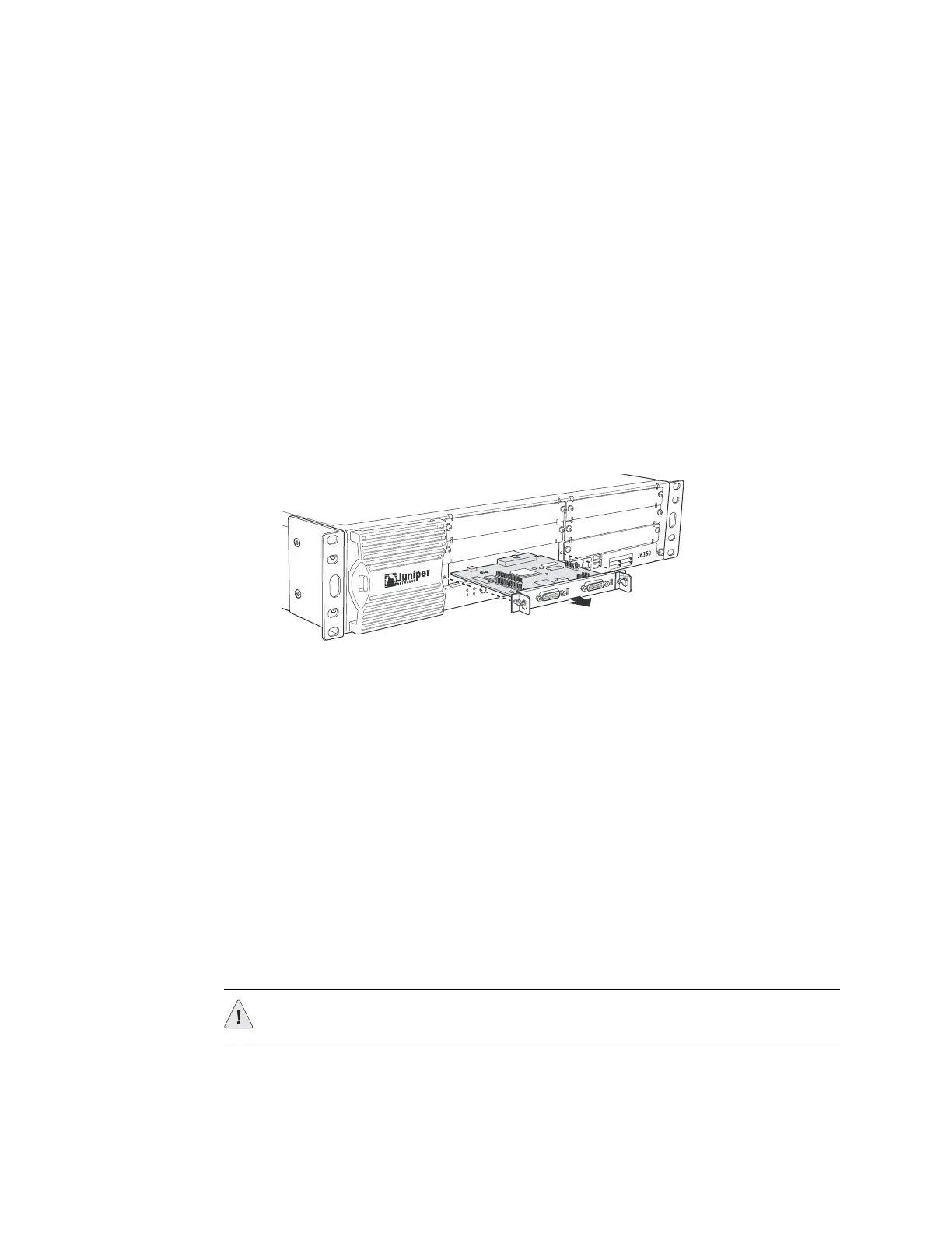
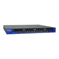
8. Grasp the handles on each side of the PIM faceplate, and slide the PIM out of
the device (Figure 24). Place it in the electrostatic bag or on the antistatic mat.
Figure 24: Removing/Installing a Physical Interface Module
9. If you are not reinstalling a PIM into an empty slot, install a blank PIM faceplate
over the slot to maintain proper airflow.
Installing a PIM
To install a PIM, perform the following steps:
1. Attach an ESD grounding strap to your bare wrist, and connect the strap to the
ESD point on the chassis or to an outside ESD point if the device is
disconnected from earth ground.
2. Press and release the power button to power off the device. Verify that the
POWER LED blinks and then turns off.
3. Grasp the handles on each side of the PIM faceplate, and align the notches in
the connector at the rear of the PIM with the notches in the PIM slot in the
device. Then slide in the PIM until it lodges firmly in the device.
4. Tighten the screws on each side of the PIM faceplate using a 1/8-inch flat-tip
screwdriver.
5. Insert the appropriate cables into the cable connectors on the PIM.
1
4
5
6
2
3
TO
LS
N
M
U
EBR
E
E
E
E
O
P
R
EW
O
P
R
E
W
T
S
S
U
T
A
MR
A
L
A
A
H
T
E
SER
ELOSNOC
XU
A
B
SU
1
0
GIF
N
O
C
0
00
1/0
0
1/0
1
ES
R
A
I
L
0 T
R
OP
TS A S
U
T
RO
P
1
T
T
S A S
U
T
CAUTION: Slide the PIM straight into the slot to avoid damaging the components
on the PIM.