(No.PA045<Rev.001>)1-19
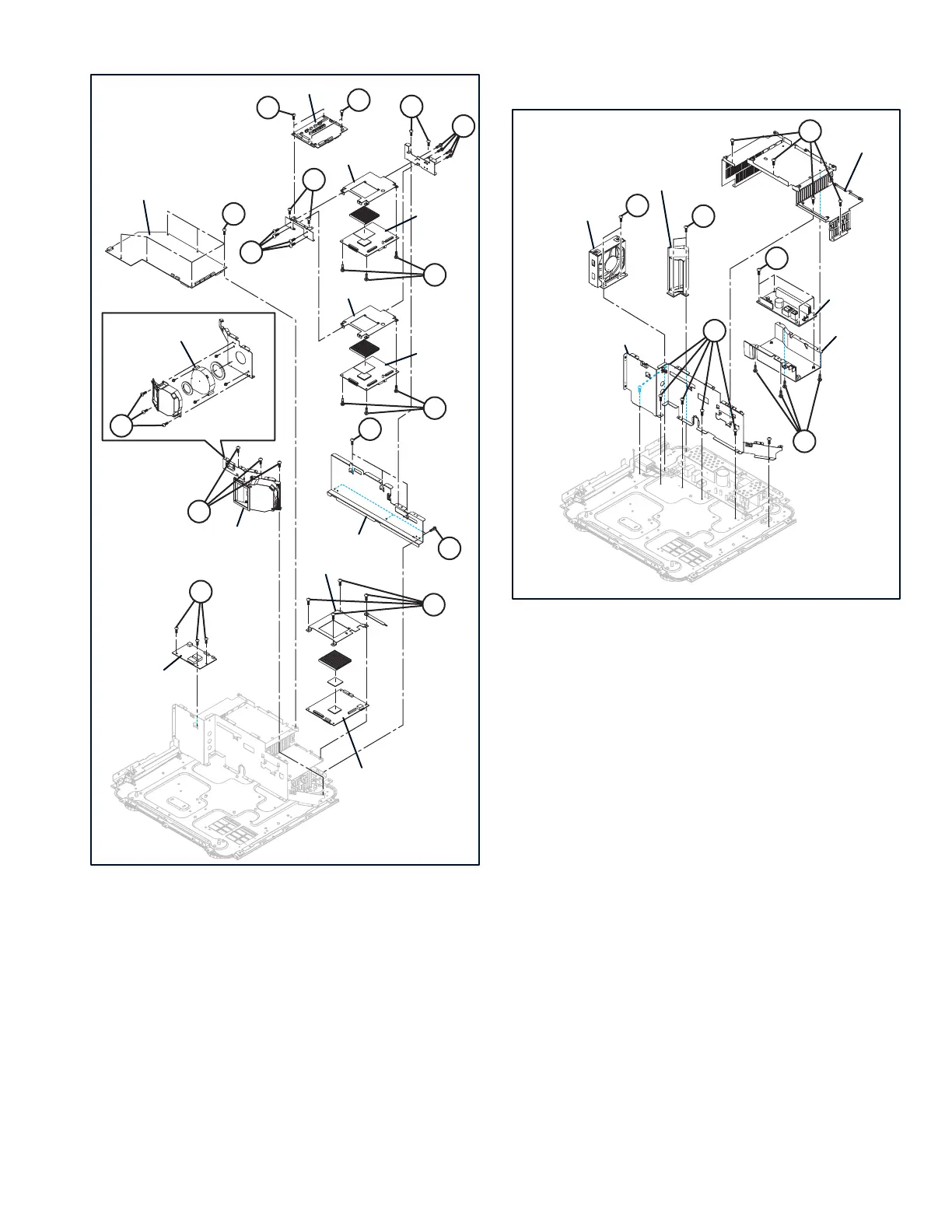
Fig.3-5
3.2.34 REMOVING THE BLIND EXHAUST (Fig.3-6)
(1) Remove the 2 screws [A], then remove the BLIND EX-
HAUST.
3.2.35 REMOVING THE EXHAUST FAN (Fig.3-6)
(1) Remove the 2 screws [B], then remove the EXHAUST
FAN.
3.2.36 REMOVING THE BALLAST PWB (Fig.3-6)
(1) Remove the 3 screws [C], then remove the SHIELD POW-
ER.
(2) Remove the 4 screws [D], then remove the DUCT BAL-
LAST.
(3) Remove the 4 screws [E], then remove the BALLAST
PWB.
3.2.37 REMOVING THE SHIELD CENTER (Fig.3-6)
(1) Remove the 6 screws [F], then remove the SHIELD CEN-
TER.
Fig.3-6
3.2.38 REMOVING THE POWER PWB (Fig.3-7)
(1) Remove the 4 screws [A], then remove the POWER PWB.
3.2.39 REMOVING THE AC CONNECTOR (Fig.3-7)
(1) Remove the 2 screws [B], then remove the AC CONNEC-
TOR.
3.2.40 REMOVING THE LAMP COVER PWB (Fig.3-7)
(1) Remove the 1 screw [C], then remove the LAMP COVER
PWB.
3.2.41 REMOVING THE BOTTOM CHASSIS (Fig.3-7)
(1) Remove the FOOT.
(2) Remove the 14 screws [D], then remove the BOTTOM
CHASSIS.
KK
KK
EE
FF
HH
HH
JJ
AA
FF
GG
GG
EE
BB
PROCESSOR PWB
SHIELD RIGHT
DD SUB PWB
MD PWB]
(TOP)
MD PWB
(BOTTOM)
SHIELD MD
SHIELD MD
SHIELD CW
LD PWB
CW PWB
DD COOLING
FAN
DD COOLING
FAN UNIT
CC
DD
BB
AA
EE
CC
DD
FF
EXHAUST FAN
BLIND EXHAUST
DUCT BALLAST
BALLAST PWB
SHIELD CENTER
SHIELD POWER
 Loading...