1-44 (No.MB368)
3.4.2 Removing the head amplifier & mechanism control board
(See Fig.4)
(1) Turn over the cassette mechanism assembly and remove
the three screws A attaching the head amplifier & mecha-
nism control board.
(2) Disconnect the flexible wire from connector CN31
on the
head amplifier & mechanism control board.
(3) Disconnect connector CN32
of the head amplifier & mech-
anism control board from connector CN1
on the reel pulse
board.REFERENCE: If necessary, unsolder the 4-pin wire
soldered to the main motor.
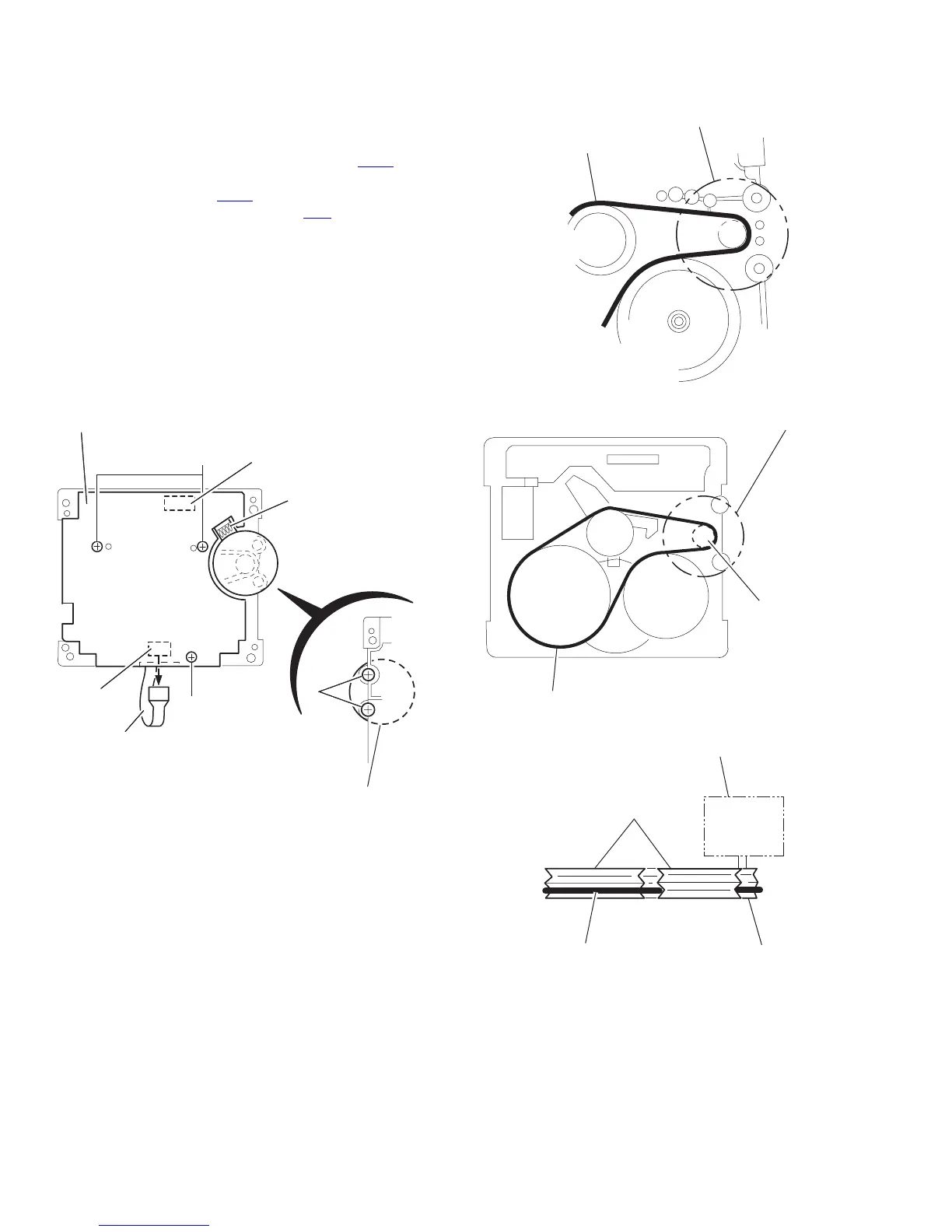
3.4.3 Removing the main motor
(See Fig.4~7)
(1) Remove the two screws B .
(2) Half raise the motor and remove the capstan belt from the
motor pulley.
ATTENTION:
Be careful to keep the capstan belt from grease. When reas-
sembling, refer to Fig.6 and 7 for attaching the capstan belt.
Fig.4
Fig.5
Fig.6
Fig.7
Head amplifier & mecha control board
AA
A
B
CN31
CN32
4pin wire
Flexible wire
Main motor assembly
Main motor assembly
Capstan belt
Main motor assembly
Capstan belt
Motor pulley
Main motor assembly
Capstan belt
Fly wheel
Motor pulley
 Loading...