1-12
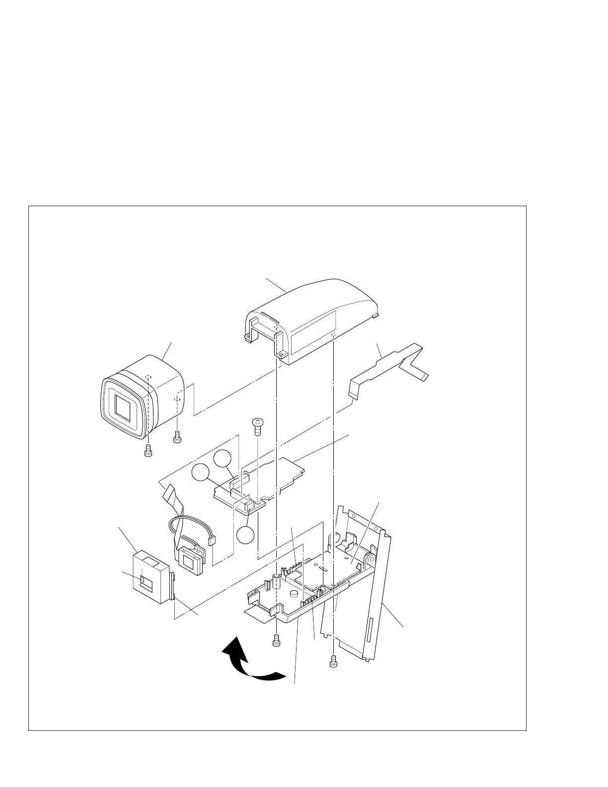
1.6 DISASSEMBLY/ASSEMBLY OF ELECTRONIC
VIEWFINDER (VF)
1.6.1 Disassembly/Assembly of B/W VF
Note
1: When remove the B/W VF, leave the hinge assem-
bly VF), bracket (VF) and VF case (L) as they are
fitted to the VF. For remove the hinge assembly (VF)
and bracket (VF), refer to the exploded view (section
5).
1. Raising the VF assembly, remove two screws (1, 2) and
then remove the eye piece assembly.
2. Remove two screws (3, 4) and then remove the VF case
assembly (U) while unhooking it from L1 and L2.
Fig. 1-6-1
Note
2: When assembling, move the FPC inwards with a wire
paying careful attention to it not to break it.
3. Pull the wire out of the connector V.
4. Unlocking the connector W, pull out the FPC.
5. While holding the holder (LCD) by hand, remove the LCD
module together with the backlight.
Note
3: When assembling, set the bosses (L3, L4) of the
holder (LCD) in the groove.
6. Remove one screw (5) and then remove the VF (B/W)
board assembly.
HINGE ASSY(VF)
VF CASE(L)
VF CASE(U)
EYE PIECE ASSY
1
(S20)
(L4)
(L3)
(L2)
BRACKET(VF)
FPC
HOLDER(LCD)
B/W VF BOARD
ASSY
✽
4
(S20)
✽
3
(S20)
✽
2
(S20)
✽
5
(S21)
✽
W
X
V
(L1)
✽ : 0.07N·m (0.7kgf·cm)
 Loading...