2-17
Table 2-3-1
2.3 PROCEDURE OF COMPATIBILITY AND P.B. EQ.
(ERROR RATE) ADJUSTMENTS
2.3.1 Precautions
Prior to starting disassembling and adjusting work, be sure to
make a backup copy of the data stored in the EEPROM (IC1003
on the MAIN board) for the “EEPROM utility” of the SSS soft-
ware.
Table 2-3-1 shows important service points for adjustment of
P.B. EQ. (error rate).
Replacement of Necessary Necessary Necessary Necessary
DRUM
Replacement of parts of Necessary Unnecessary Unnecessary Check
tape transport system
Repair of parts of tape Necessary Unnecessary Unnecessary Check
transport system
(DRUM)
Replacement of IC3501 Unnecessary Unnecessary Necessary Check
(SECOND board,
PRE/REC amp)
Replacement of MAIN Unnecessary Necessary Necessary Necessary
BOARD
Adjustment item
Linearity
adjustment
P.B. Switching
Point
adjustment
Head Recording
Current
adjustment
Error rate
(P.B. EQ).
adjustment
(SP/LP)
Service point
Note 1
Note 1
Note 1
Note 2
Note 1:
Linearity adjustment is needed only after replacement
of the drum or replacement/repair of the TU/SUP guide
rail.
Note 2:
After replacement of the MAIN board, be sure to write
the original data on the EEPROM of the new MAIN
board. After data writing, adjust the camera section.
When the MAIN board is replaced for the reason of
communication failure, install the original EEPROM on
the new MAIN board.
If adjustment is needed for two or more items, proceed in ad-
justment of respective items in the following order.
2.3.3 Linearity adjustment
2.3.4 PB switching point adjustment
2.3.5 Head REC current adjustment
2.3.6 P.B. EQ. (error rate) adjustment (both in SP and LP)
2.3.2 Adjustment standard
Note :
For details of the test instruments, tools and jigs re-
quired for adjustment, refer to pages 1-2, 1-3 and 2-1
of this manual.
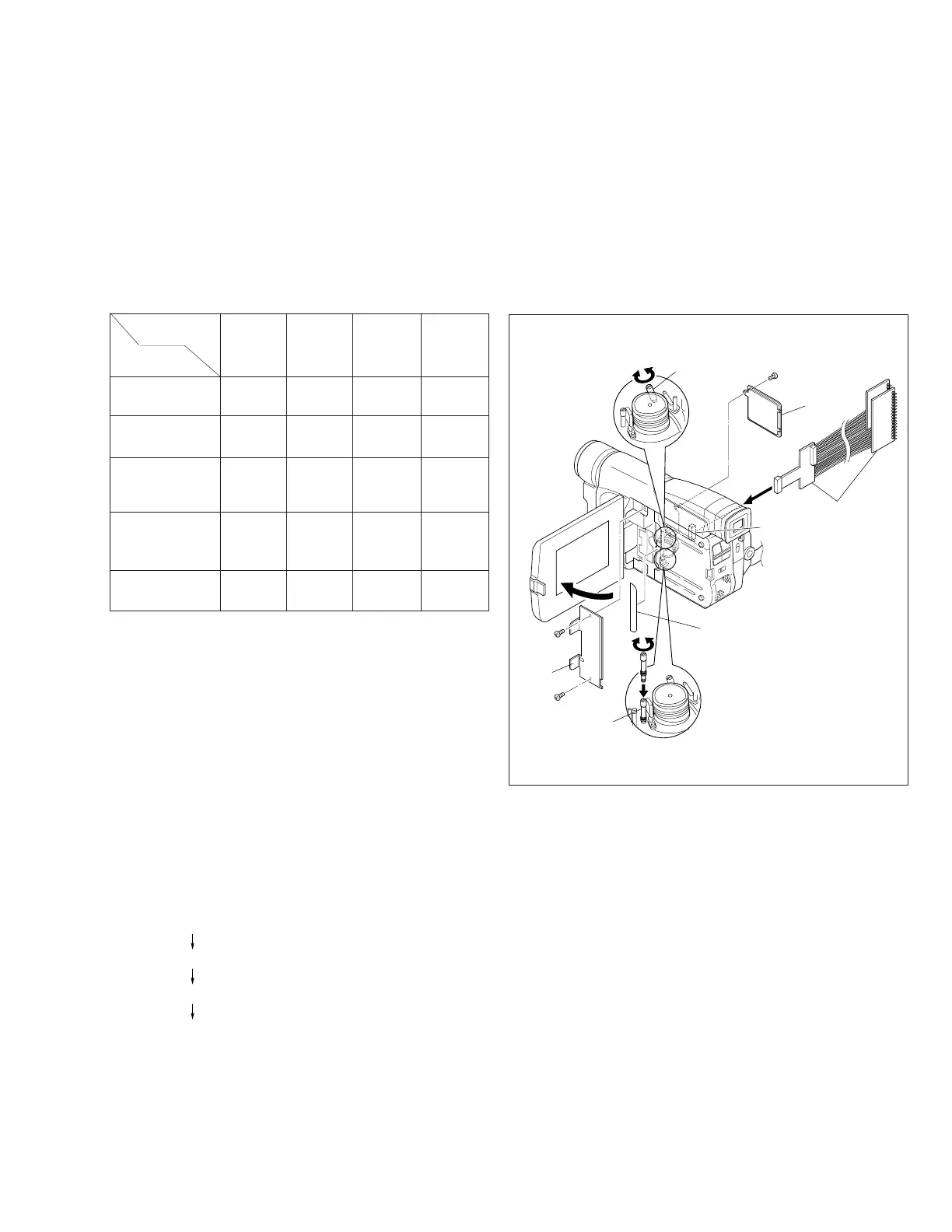
1. Remove the cover (CC).
Note :
Carefully remove the cover not to scratch the exterior
of the camera. Since the cover (CC) shall be restored
to the original position after adjustment, be very care-
ful not to soil its adhesive surface.
2. Open the monitor assembly. Remove two screws (1, 2)
and then remove the upper case (2).
3. Remove one screw (3) and then remove the cover (jig).
Fig. 2-3-1
1
(S4)
2
(S4)
CN105
Jig connecror
cable
(YTU93082C)
Pole base
assembly
3
(S5)
Cover
(jig)
Cover
(CC)
Guide roller
assembly
Upper
case (2)
 Loading...