3-3
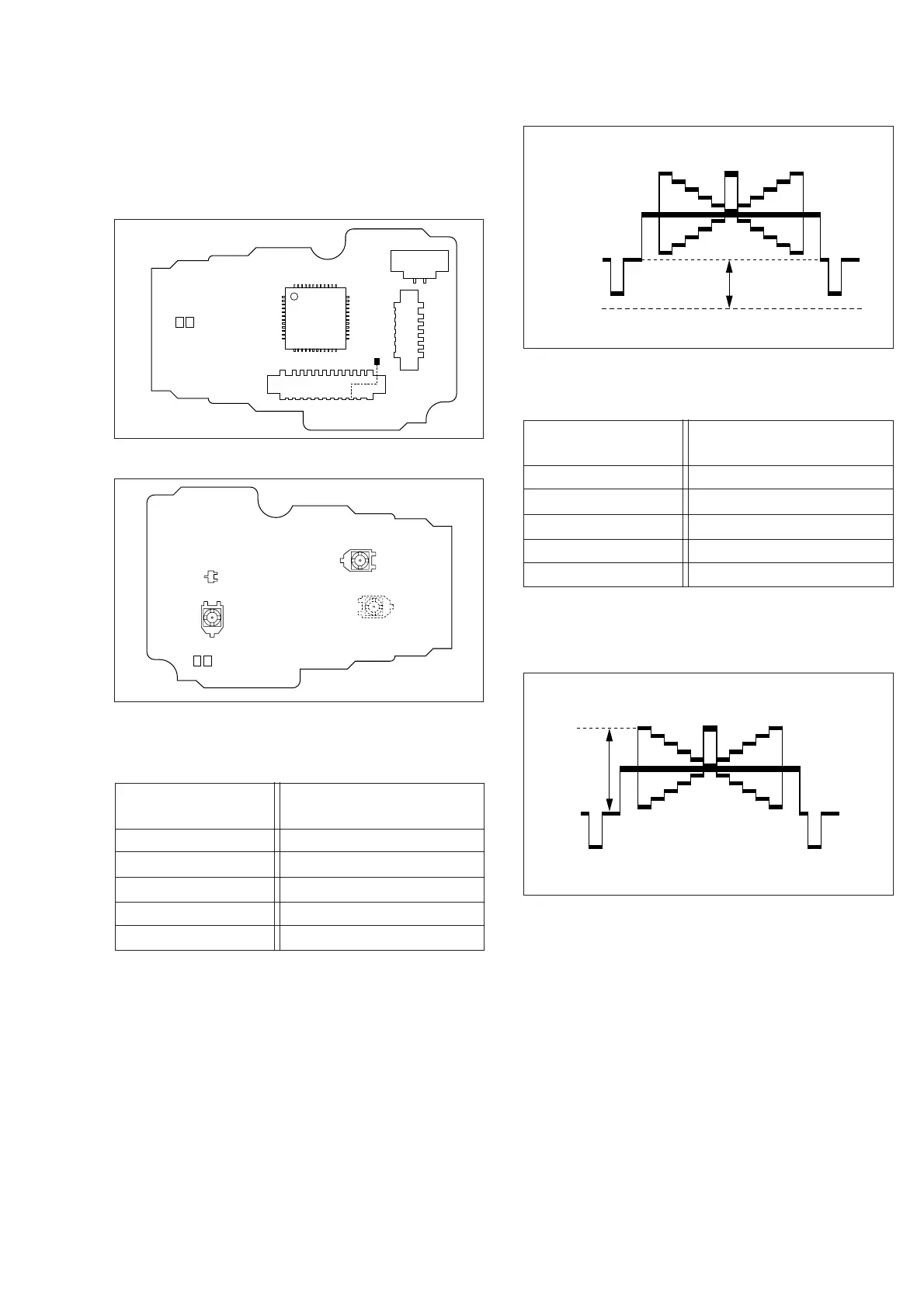
Subject • Camera picture
• Gray scale
Mode • EE
Equipment • Oscilloscope
Measurement point • CN7002 pin 4 (VIDLO)
Adjustment part • VR7002 (Black level)
Specification • "A"=2.5 ± 0.05 VDC
1) Observe waveform at pin 4 of the CN7002.
2) Adjust VR7002 so that DC level of "A" (between the
pedestal level and GND, see Fig. 3-4-3) of a waveform
becomes 2.5 ± 0.05 V DC.
3.4.1 Black level
3.4 ELECTRONIC VIEWFINDER (E. VF) ADJUSTMENT
Notes:
Unless otherwise specified, all measurement points
and adjustment parts are located on E. VF board.
Fig. 3-4-1 E. VF board (A)
Fig. 3-4-2 E. VF board (B)
1 0 B/W VF PWB
YB20861-01-01
19
CN7002
IC7001
CN7001
ZP7008
CN7003
1
2413
3748
1
12
36
25
10
2
9
21
1
20 2
1 0 B/W VF PWB
YB20861-01-01
VR7002
BLACK LEVEL
Q7001
VR7001
GAIN
Fig. 3-4-3 Black level
Subject • Camera picture
• Gray scale
Mode • EE
Equipment • Oscilloscope
Measurement point • CN7002 pin 4 (VIDLO)
Adjustment part • VR7001 (Gain)
Specification • "A"=2.7 ± 0.05 Vp-p
1) Observe waveform at pin 4 of the CN7002.
2) Adjust VR7001 so that level of "A" (see Fig. 3-4-4) of a
waveform becomes 2.7 ± 0.05 Vp-p.
3.4.2 Gain
Fig. 3-4-4 Gain
"A" = 2.5±0.05VDC
"A"
H.rate
GND(0V)
"A" = 2.7±0.05VP-P
"A"
H.rate
 Loading...