2-18
Fig. 2-3-2
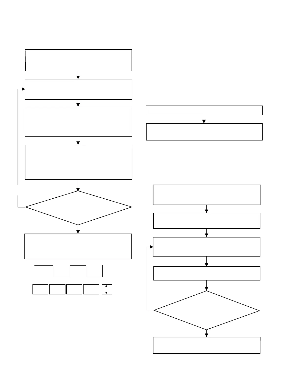
2.3.3 Linearity adjustment
Procedure of linearity adjustment is shown by the following
flowchart.
Note 3:
In case of the VHS tape recorder, the first tracking point
can be locked by means of CTL pulse and DRUM FF
when the automatic tracking (AT) function is off, be-
cause the VHS tape recorder has an A/C head. There-
fore, the linearity of the VHS tape recorder is adjust-
able even when the AT is off.
On the other hand, the linearity of the DVC cannot be
adjusted when the automatic tracking finding (ATF)
function is inactivated, because the DVC has no A/C
Play the alignment tape. Then, turn on the ATF
(automatic tracking finding) switch for the “VTR deck”
of “Remote control utility” of the SSS software.
While triggering an oscilloscope with a signal from pin
20 (HID) of CN105 on the MAIN board, observe the
waveform at pin 5 (ENV OUT) of CN105 with the
oscilloscope (set for the positive [+] slope).
If the P.B. ENV. waveform is ideally stable and it ideally
varies with change of tracking, it is recognizable that
the linearity is completely adjusted. Finally, check both
the audio and video waveforms for the linearity while
playing back a previously recorded tape.
Check to see whether the P.B.
ENV. waveform is ideally
stable and it ideally varies with
change of tracking, or not.
Yes
No
Repeat the above steps
depending on the situation.
Make sure that the waveform observed at pin 5 (ENV
OUT) of CN105 is linear and parallel as a whole
without extreme drop and irregularity in the level. If the
linearity of the waveform is poor or there is extreme
level drop in the waveform, adjust the guide roller by
turning it with a roller driver.
Turn off the ATF (automatic tracking finding) switch.
Use the “VTR deck” of “Remote control utility” of the
SSS software (Note 4). While observing the waveform
at pin 5 (ENV OUT) of CN105, check to see if the
parallelism and linearity of the waveform vary as a
whole with change of tracking as shown in Fig. 2-3-2.
PB ENV
waveform
Adjust for
parallel
level change.
HID waveform
CH1
CH2
head. When the ATF of the DVC is off, its tracking op-
eration is effectuated only for the speed control sys-
tem. Therefore, as time elapses, the DVC gradually
fails in the servo control and it becomes hard to adjust
the linearity.
Note 4:
In practice, if linearity adjustment is performed within
a few minutes after the ATF is switched off, the state
(ATF off) may be left out of consideration, because the
speed servo of the DVC functions when the ATF is off.
2.3.4 PB switching point adjustment
Procedure of PB switching point adjustment is shown by the
following flowchart.
2.3.5 Head REC current adjustment
Procedure of head REC current adjustment is shown by the
following flowchart.
Start the alignment tape, and the PB switching point of
the deck is automatically adjusted by the “VTR deck”of
“Remote control utility” of the SSS software.
Set the alignment tape into the cassette compartment
While recording the built-in color bar signal (or EE
picture), adjust the “Head REC current” of the “VTR
deck” of the“Remote control utility” to be the value
(420 mV) specified
Yes
No
Check the error rate while playing back th
that was adjusted for
“head REC current” in reco
Check the error rate while playing back the recorded
parts whose data of “head REC current” were changed.
While changing the “head REC current” data by increasing
and decreasing the value at a unit of 10h, record the built-in
color bar signal (or EE picture) for 1 minute each. Note 5
If the observed error rate is minimum (approximation to
the standard value), it is considered that the REC current
adjustment is complete.
If the observed error
rate is minimum (approximation to the
standard value), it is considered that the
REC current adjustment is complete.
Note 6
Note 6
 Loading...