3-2
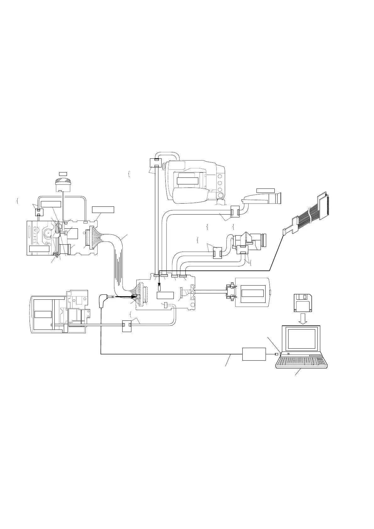
2. Setup with patch cords and jig connector cables
NOTE:
Fig. 3-3-2 shows an example of expansion setup that facilitates
inspection of major boards because main components are
connected by means of patch cords and jig cables. For
proceeding to electrical adjustment in such the setup,
disassemble the set at a certain level required for the current
adjustment objectives referring to the section 1 “DISASSEMBLY”
and properly set up the expanded set and test instruments.
Service support s
YTU94057-41
Jig connector
YTU93082C
RS232C
port
PC cable
QAM0099-002
Personal computer
MENU
YTU94074-15
YTU94077-15
LOWER CASE
ASSY
E. VF ASSY
LCD MONITOR
ASSY
MAIN PWB
ASSY
REAR OPE
UNIT
YTU94074-10
for B/W VF
or
YTU94077-10
YTU94074-20
for COLOR VF
YTU94077-20
YTU94074-18
YTU94077-18
YTU94126A-100
YTU94074-6
YTU94077-6
MECHANISM
ASSY
MECHANISM
ASSY
MIC
YTU94074-10
YTU94077-10
SECOND PWB
ASSY
CN401
CN501
CN502
CN101
CN110
CN102
CN109
CN104
CN105
JIG CONN
CN106
CN107
CN301
YTU94074-22
YTU94077-22
J503
JLIP
CN302
CN404
CN503
CN504
Fig. 3-3-2 Setup for electrical adjustment with personal computer (II)
 Loading...