2-8
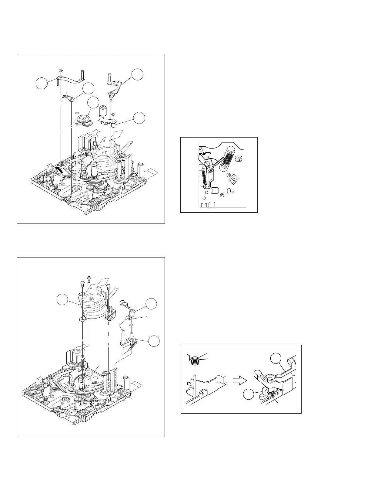
Fig. M3
3. 4 Tension arm assembly/ 5 Release guide assembly
6 Idler arm assembly/ 7 Guide arm assembly
8 Pinch roller arm assembly
Note 4:
When removing the reel cover assembly, pay heed to release
guide assembly and guide arm assembly. For, the guide arm
assembly is just inserted into the slide deck assembly from
the upside and it is apt to come off after the reel cover as-
sembly is removed.
Note 27:
Reassemble the tension arm assembly to the mechanism as
the pad arm assembly is moved to the extent in the direction
of the arrow.
Fig. M4
4. 9 Cleaner arm assembly/ 0 Slant pole arm assembly
! Drum assembly
Note 5:
When removing the cleaner arm assembly, it is recommended
to remove the slant pole arm assembly together with it except
the case of a single unit replacement, because the hook (L5)
is hard to disengage.
Note 6:
When the shield is applied, carefully remove the drum final
assembly because the drum is stuck to the shield.
Note 26:
How to set the coil spring (P2).
4
(W2)
(W1)
(W1)
7
8
6
5
Note 27
Note 4
11
(W1)
(L5)
(P1)
(L6)
8
(S2)
7
(S2)
9
(S2)
9
10
(P2)
Note 5
Note 26
Note 6
(P2)
9
10
(P2)
 Loading...