15
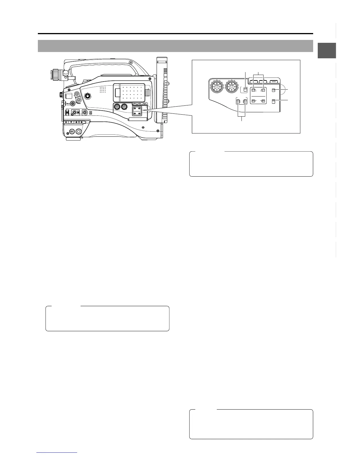
2. CONTROLS, INDICATORS AND CONNECTORS
MONITOR
EDITSEARCH
FILTER
STATUS
SHUTTER
MENU
AUTO IRIS
BACK L
NORMAL
SPOT L
STRETCH
NORMAL
COMPRESS
FULL AUTO BLACK LOLUX
MODE
POWER
ON OFF
VTR
OPEN
VTR
CAM
1
3200K
5600K
5600K
5600K
ND
/
/
ND
2
.3
.4
1
8
1
64
CH-1
AUDIO INPUT
AUDIO SELECT
CH-2
CH-1 CH-2
FRONT
REAR
AUTO
MANUAL
AUDIO
LEVEL
CH-1 CH-2
PULL
OPEN
LCD BRIGHT DISPLAY
COUNTER
CH-1
AUDIO INPUT
AUDIO SELECT
CH-2
CH-1 CH-2
FRONT
REAR
AUTO
MANUAL
TC GENE.
TC
MONITOR
SELECT
AUDIO
LEVEL
AUDIO INPUT
CH-1 CH-2
CH-1
MIX
CH-2
FRONT REAR
LINE
MIC
+48V
PRST
REGEN FREE
REC
UB
LCD BRIGHT DISPLAY
!1
!2
!3
!4
!0
0
[CH-1/CH-2 AUDIO INPUT] CH-1/CH-2 audio input
selector switch
This switch is used to select the input sound of the CH1 or
CH2 audio channel. It is selected for each of the CH1 and
CH2 channels.
FRONT : The sound from the FRONT AUDIO IN connector
on the front side section is input.
REAR : The sound from the REAR AUDIO IN connector
on the rear side section is input.
!
[FRONT/REAR AUDIO INPUT] Front/rear audio
input signal selector switch.
This switch is used to select the input sound signal from
the FRONT AUDIO IN connector and the REAR AUDIO IN
connector.
LINE : Set to this position when connected to audio
equipment, etc. The reference input level is +4 dBs.
MIC : Set to this position when the microphone is
connected. The reference input level is -60 dBs.
+48V : Set to this position when a microphone requiring
+48 V power supply (phantom microphone, etc.) is
connected. This connector supplies +48 V DC
current.
When using the provided microphone connected
to the FRONT AUDIO IN connector, set the FRONT
AUDIO INPUT switch to this setting.
CAUTION:
When connecting a component that does not require
+48 V power supply, make sure that the switch is not
set to +48V before the component is connected.
@
[MONITOR SELECT] Audio monitor selector switch
This switch is used to select the monitor sound output and
playback sound output from the monitoring loudspeaker
1
or the PHONES
5
jack on page 18.
CH-1 : The CH1 channel audio is output.
MIX : CH1 and CH2 channel audio are output mixed.
When this setting is selected, the menu screen can
be used to select whether the mixed sound or stereo
sound should be output via the PHONES jack.
(AUDIO MONITOR item on the AUDIO/VIDEO
menu screen)
When AUDIO MONITOR in the AUDIO/VIDEO
menu screen is set to “STEREO”, only the audio of
CH-1 is output from the monitoring loudspeaker.
CH-2 : The CH2 channel audio is output.
☞ See “Outputting CH-3, CH-4 Channel Audio” on page 59.
☞ See “AUDIO/VIDEO Menu Screen” on page 72.
View with cover open.
CAUTION:
Make sure to move switches all the way. Do not leave
a switch stopped in a midway position. Noise will be
generated and operation irregularities will occur.
#
[COUNTER] Counter display switch
Selects the contents displayed on the TC counter of the
LCD monitor or in the viewfinder. (This switch works when
the TC/UB item on the LCD/VF (2/2) menu screen is set to
ON.)
TC : Set to this position to display time code values.
UB : Set to this position to display the user’s bits values.
$
[TC GENE.] Time code generator setting switch
Switch for setting the time code generator to preset mode
or regeneration mode. It is also used to select the time code
run mode when the preset mode is selected.
PRST-FREE : The preset mode is selected, and the time
code run mode becomes the FREE run
mode.
Set to this position to record with the time
code or user’s bits set anew (preset). In this
setting, the time code always operates in the
run mode.
* If this setting is used when recording scenes one after
another, the time codes become discontinuous at the
transition points between scenes.
PRST-REC : The preset mode is selected, and the time
code run mode becomes the REC run mode.
Set to this position to record with the time
code or user’s bits set anew (preset). The
time code operates in the run mode during
recording only. If this setting is used when
recording scenes one after another, the time
codes are recorded as continuous time
codes.
REGEN : Regeneration mode, in which the unit reads
existing time codes on the tape and records
time codes in continuation of the existing
ones. Set to this position when you want to
add additional time codes to time codes
already recorded on the tape.
MEMO:
Preset of time code and user’s bits is performed on the
TC/UB/CLOCK menu.
☞ See “TIME CODE OPERATION” on page 62.
☞ See “TC/UB/CLOCK Menu Screen” on page 75.

 Loading...