56
7. SHOOTING OPERATION
7-5 Recording the Color Bars
MONITOR
EDITSEARCH
FILTER
STATUS
SHUTTER
MENU
AUTO IRIS
BACK L
NORMAL
SPOT L
STRETCH
NORMAL
COMPRESS
FULL AUTO BLACK LOLUX
MODE
POWER
ON OFF
VTR
OPEN
VTR
CAM
1
3200K
5600K
5600K
5600K
ND
/
/
ND
2
.3
.4
1
8
1
64
CH-1
AUDIO INPUT
AUDIO SELECT
CH-2
CH-1 CH-2
FRONT
REAR
AUTO
MANUAL
AUDIO
LEVEL
CH-1 CH-2
PULL
OPEN
LCD BRIGHT DISPLAY
POWER
ON OFF
VTR
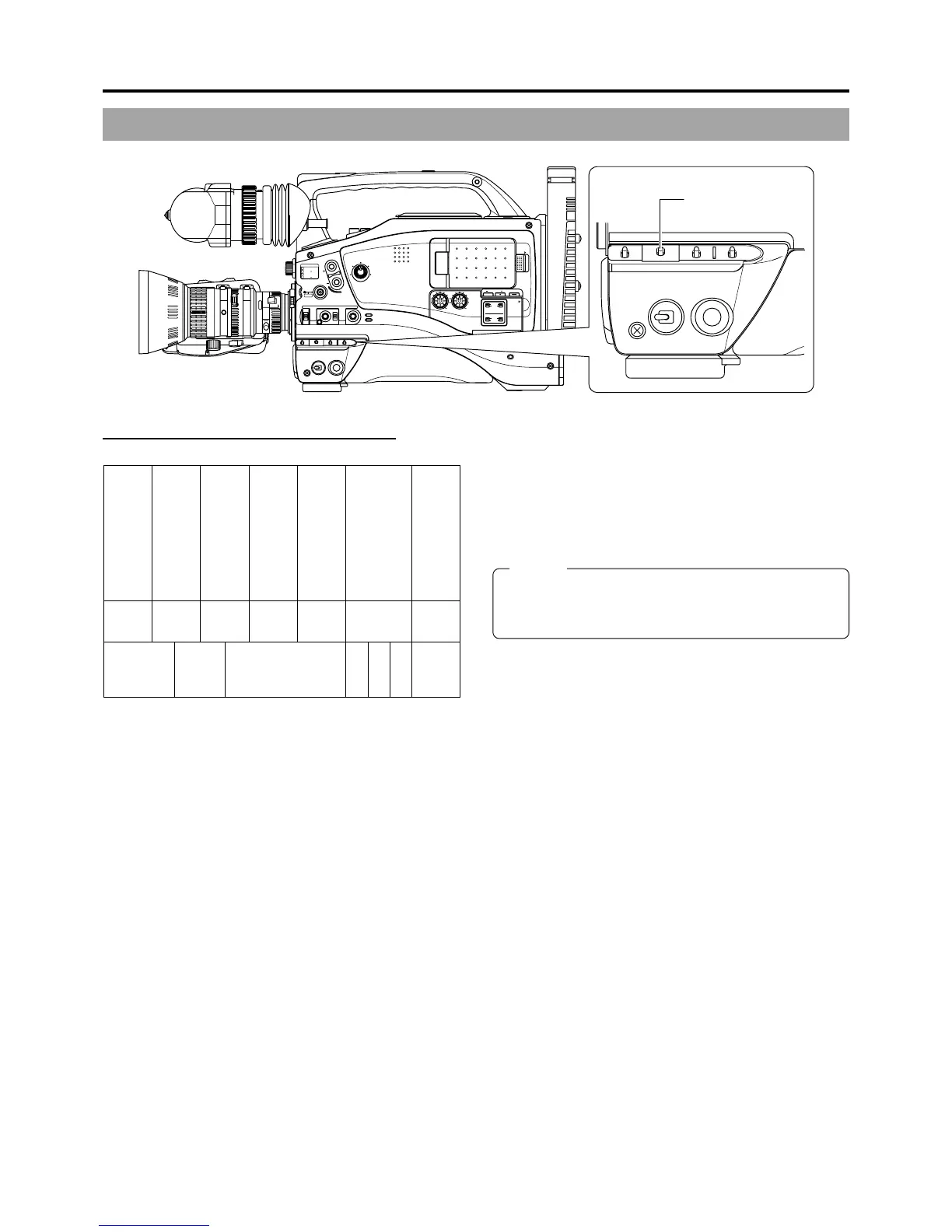
OUTPUT switch
Color bar signal of the built-in signal generator
An SMPTE standard color bar is output.
Whether the camera image should be output or whether the
color bar of the built-in signal generator should be output can
be selected during record-standby and recording.
■ To output the color bar, set the OUTPUT switch to the
BARS side.
■ To output the camera image, set the OUTPUT switch to
the CAM AUTO KNEE ON/OFF side.
MEMO:
Whether or not the audio reference signal should be output
while the color bar is output can be selected with the TEST
TONE item on the AUDIO/VIDEO menu screen.
White Yellow Cyan Green Magenta Red Blue
Blue Black Magenta Black Cyan Black White
Black White Black

 Loading...