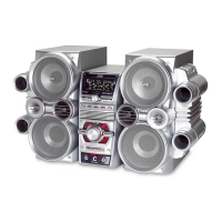
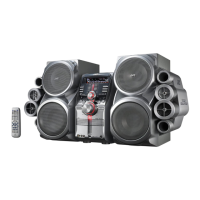
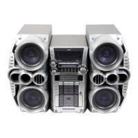
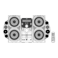
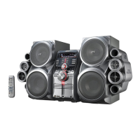
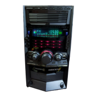
HX-Z1
27
SECTION 4
Adjustment method
4.1 Measurement Instruments Required for Adjustment
(1) Low frequency oscillator
This oscillator should have a capacity to output 0dBs to
600OHM at an oscillation frequency of 50Hz-20kHz.
(2) Attenuator impedance : 600OHM
(3) Electronic voltmeter
(4) Distortion meter
(5) Frequency counter
(6) Wow & flutter meter
(7) Test tape
(8) Blank tape
(9) Torque gauge : For play and back tension
FWD(TW2111A), REV(TW2121a) and
FF/REW(TW2231A)
(10) Test disc: CTS-1000
4.2 Measurement conditions
Power supply voltage
Reference frequency and
4.3 Radio Input signal
4.4 Tuner section
Reference measurement
4.5 Standard measurement position of volume
Adjustment of main volume to reference output
VOL : 28
Precautions for measurement
(1) Apply 30pF and 33kOHM to the IF sweeper output side
and 0.082µF and 100kOHM in series to the sweeper in-
put side.
(2) The IF sweeper output level should be made as low as
possible within the adjustable range.
(3) Since the IF sweeper is a fixed device, there is no need
to adjust this sweeper.
(4) Since a ceramic oscillator is used, there is no need to
perform any MIX adjustment.
(5) Since a fixed coil is used, there is no need to adjust the
FM tracking.
(6) The input and output earth systems are separated.
In case of simultaneously measuring the voltage inboth
of the input and output systems with an electronic volt-
meter for two channels, therefore, the earth should be
connected particularly carefully.
(7) In the case of BTL connection amp., the minus terminal
of speaker is not for earthing. Therefore, be sure not to
connect any other earth terminal to this terminal. This
system is of an BTL system.
(8) For connecting a dummy resistor when measuring the
output, use the wire with a greater code size.
(9) Whenever any mixed tape is used, use the band pass
filter (DV-12).
VT703L : Head azimuth
VT712 : Tape speed and running unevenness
(3kHz)
VT724 : Reference level (1kHz)
TYPE áT: AC-225
TYPE áU: AC-514
AC120V (60Hz) : Ver.J,C
Reference output : Speaker: 0.775V/4OHM
: Headphone : 0.077V/32OHM
input level ------------------------------------------1kHz, AUX : -8dBs
Measurement output terminal -----------------at Speaker J3002
* Load resistance ------------------------------ 4OHM
AM frequency -------------------------------------400Hz
AM modulation ------------------------------------30%
FM frequency --------------------------------------400Hz
FM frequency deviation -------------------------22.5kHz
Aversion: FW 87.5MHz~108.0MHZ
AM 522KHz~1629KHz
UW,UJ version: FM 87.5MHz~108.0MHz
AM 531KHz~1710KHz(9KHz step)
AM 530KHz~1710KHz(10KHz step)
Voltage applied to tuner-------------------------+B : DC5.7V
VT : DC 12V
output----------------------------------26.1mV(0.28V)/3OHM
Input positions-----------------------AM : Standard loop antenna
FM : TP1 (hot) and TP2 (GND)
Function switch-----------------------------------------to Tape
Beat cut switch----------------------------------------- to Cut
Super Bass/Active hyper Bass---------------------to OFF
Bass Treble--------------------------------------------- to OFF
Bass Treble--------------------------------------------- to OFF
 Loading...