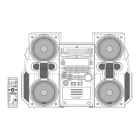
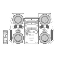
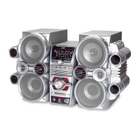
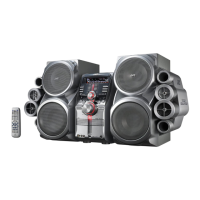
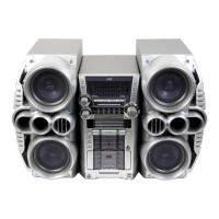
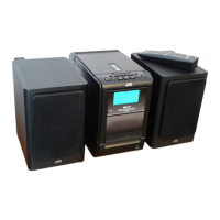
HX-Z1
53
5.22MN35510AL (IC561) : Digital servo & Digital signal processor
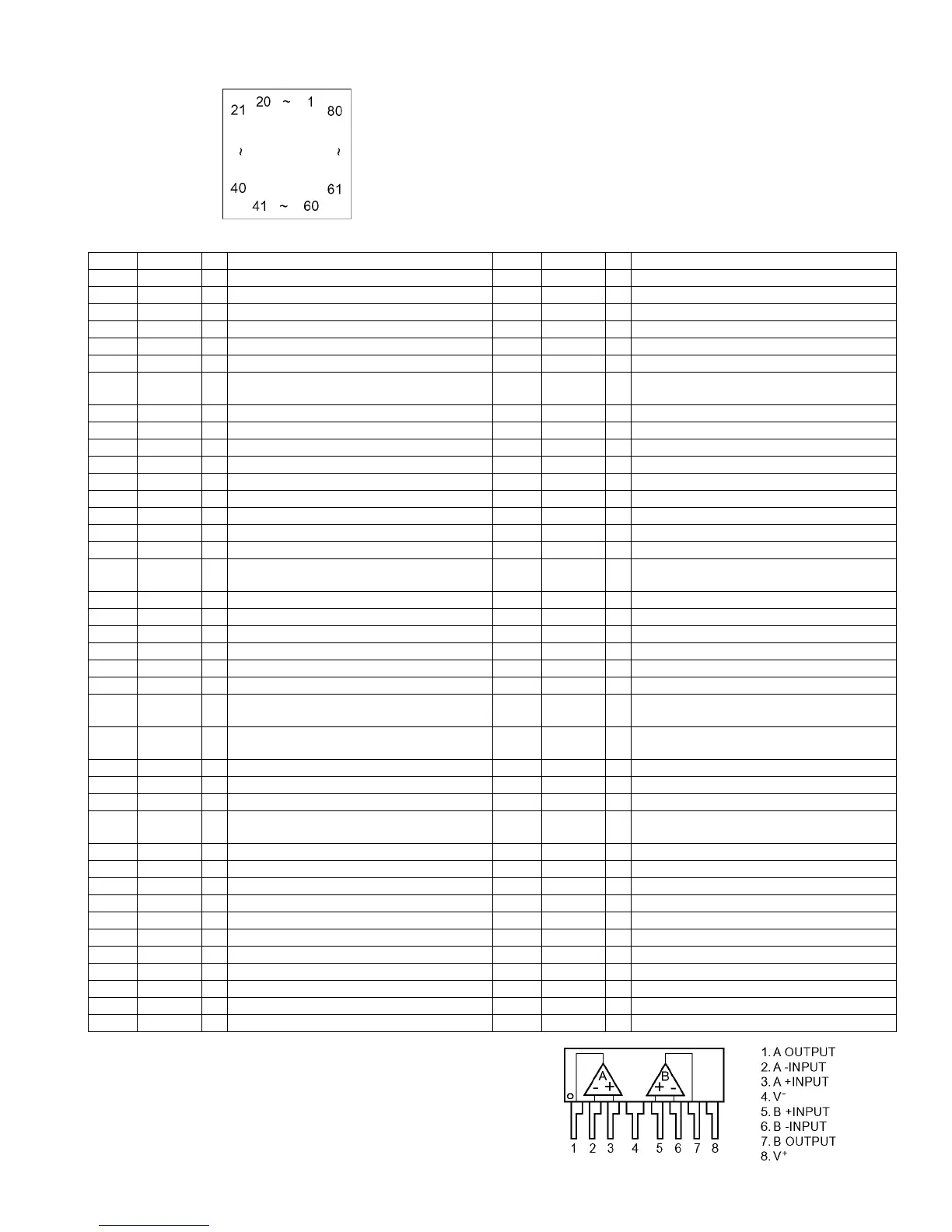
• Terminal Layout
• Pin function
5.23 NJM4580L (IC902) : Dual operational amplifier
PinNo. symbol I/O Function PinNo. symbol I/O Function
1 BCLK O Not used 41 TES I Tracking error shunt signal output(H:shunt)
2 LRCK O Not used 42 PLAY O Not used
3 SRDATA O Not used 43 WVEL O Not used
4 DVDD1 - Power supply (Digital) 44 ARF - RF signal input
5 DVSS1 - Connected to GND 45 IREF - Reference current input pin
6 TX O Digital audio interface output 46 DRF I Bias pin for DSL
7 MCLK - Micom command clock signal input
(Data is latched at signal's rising point)
47 DSLF I Loop filter pin for DSL
8 MDATA I Micom command data input 48 PLLF I Loop filter pin for PLL
9 MLD I Micom command load signal input 49 VCOF I/O Not used
10 SENSE O Sense signal output 50 AVDD2 I/O Power supply(Analog)
11 FLOCK O Focus lock signal output Active :Low 51 AVSS2 - Connected to GND(Analog)
12 TLOCK O Tracking lock signal output Active :Low 52 EFM - Not used
13 BLKCK O sub-code - block - clock signal output 53 PCK - Not used
14 SQCK I Outside clock for sub-code Q resister input 54 PDO - Not used
15 SUBQ O Sub-code Q -code output 55 SUBC - Not used
16 DMUTE - Connected to GND 56 SBCK - Not used
17 STATUS O Status signal
(CRC,CUE,CLVS,TTSTOP,ECLV,SQOK)
57 VSS - Connected to GND(for X'tal oscillation
circuit)
18 RST I Reset signal input (L:Reset) 58 XI - Input of 16.9344MHz X'tal oscillation circuit
19 SMCK - Not used 59 X2 I Output of X'tal oscillation circuit
20 PMCK - Not used 60 VDD O Power supply(for X'tal oscillation circuit)
21 TRV O Traverse enforced output 61 BYTCK - Not used
22 TVD O Traverse drive output 62 CLDCK - Not used
23 PC - Not used 63 FLAG - Not used
24 ECM O Spindle motor drive signal (Enforced mode out-
put) 3-State
64 IPPLAG - Not used
25 ECS O Spindle motor drive signal (Servo error signal
output)
65 FLAG - Not used
26 KICK O Kick pulse output 66 CLVS - Not used
27 TRD O Tracking drive output 67 CRC - Not used
28 FOD O Focus drive output 68 DEMPH - Not used
29 VREF O Reference voltage input pin for D/A
output block (TVD,FOD,FBA,TBAL)
69 RESY - Not used
30 FBAL O Focus Balance adjust signal output 70 IOSEL - pull up
31 TBAL O Tracking Balance adjust signal output 71 TEST - pull up
32 FE I Focus error signal input(Analog input) 72 AVDD1 - Power supply(Digital)
33 TE I Tracking error signal input(Analog input) 73 OUT L O Lch audio output
34 RF ENV I RF envelope signal input(Analog input) 74 AVSS1 - Connected to GND
35 VDET I Vibration detect signal input(H:detect) 75 OUT R O Rch audio output
36 OFT I Off track signal input(H:off track) 76 RSEL - pull up
37 TRCRS I Track cross signal input 77 CSEL - Connected to GND
38 RFDET I RF detect signal input(L:detect) 78 PSEL - Connected to GND
39 BDO I BDO input pin(L:detect) 79 MSEL - Connected to GND
40 LDON I Laser ON signal output(H:on) 80 SSEL - Pull up
 Loading...