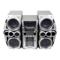
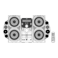
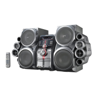
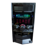
HX-Z1
23
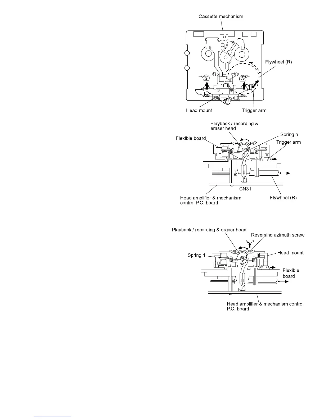
3.2 Cassette mechanism section
3.2.1 Removing the playback / recording & eraser head
(See Fig. 1 ~ 3)
(1) While shifting the trigger arms seen on the right side of the
head mount in the arrow direction, turn the flywheel R in
counterclockwise direction until the head mount has gone
out with a click (See Fig. 1).
(2) When the flywheel (R) is rotated in counterclockwise di-
rection, the playback / recording & eraser head will be
turned in counterclockwise direction from the position in
Fig. 2 to that in Fig. 3.
(3) At this position, disconnect the flexible P.C. board (outgo-
ing from the playback / recording & eraser head) from the
connector CN31 on the head amplifier & mechanism con-
trol P.C. board.
(4) Remove the flexible P.C. board from the chassis base.
(5) Remove the spring a from behind the playback / recording
& eraser head.
(6) Loosen the reversing azimuth screw retaining the play-
back / recording & eraser head.
(7) Take out the playback / recording & eraser head from the
front of the head mount.
(8) The playback / recoring & eraser head should also be re-
moved similarly according to steps 1 to 7 above.
Fig.1
Fig.2
3.2.2 Reassembling the playback / recording & eraser head
(See Fig.2, 3)
(1) Reassemble the playback head from the front of the head
mount to the position as shown in Fig. 3.
(2) Fix the reversing azimuth screw.
(3) Set the spring 1 from behind the playback / recording &
eraser head.
(4) Attach the flexible P.C. board to the chassis base, as
shown in Fig. 4.
(5) The playback / recording & eraser head should also be re-
assembled similarly to step 1 to 4 above.
Fig.3
 Loading...