Fig.28
Fig.31
Rear panel
Power amp and
supply PCB
Z(4PCS)
Fig.29
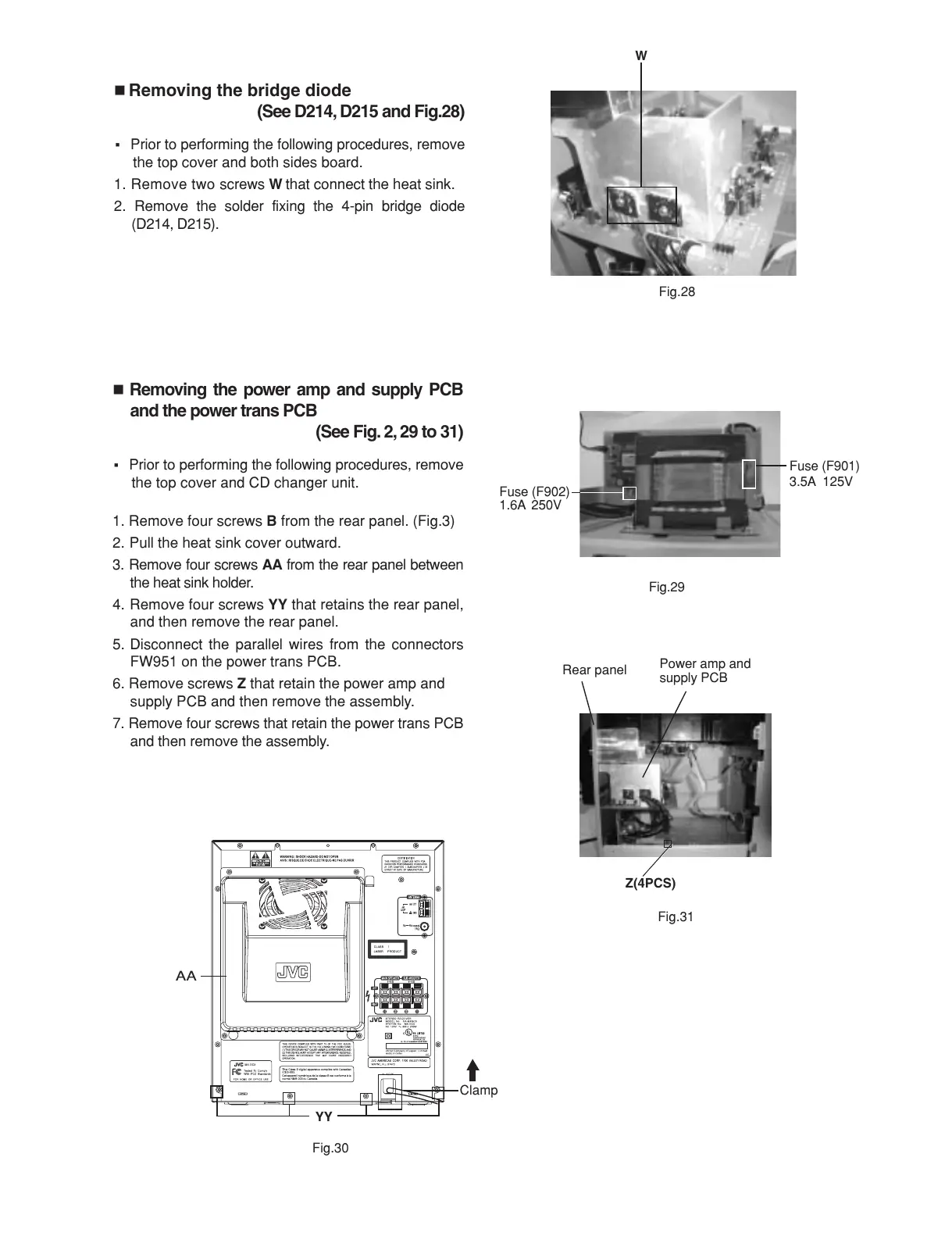
Removing the bridge diode
(See D214, D215 and Fig.28)
Prior to performing the following procedures, remove
the top cover and both sides board.
1. Remove two screws
W
that connect the heat sink.
2. Remove the solder fixing the 4-pin bridge diode
(D214, D215).
Removing the power amp and supply PCB
and the power trans PCB
(See Fig. 2, 29 to 31)
Prior to performing the following procedures, remove
the top cover and CD changer unit.
1. Remove four screws
B
from the rear panel. (Fig.3)
2. Pull the heat sink cover outward.
3. Remove four screws
AA
from the rear panel between
the heat sink holder.
4. Remove four screws
YY
that retains the rear panel,
and then remove the rear panel.
5. Disconnect the parallel wires from the connectors
FW951 on the power trans PCB.
6. Remove screws
Z
that retain the power amp and
supply PCB and then remove the assembly.
7. Remove four screws that retain the power trans PCB
and then remove the assembly.
Fig.30
YY
Clamp
AA
Fuse (F901)
3.5A 125V
Fuse (F902)
1.6A 250V
W

 Loading...