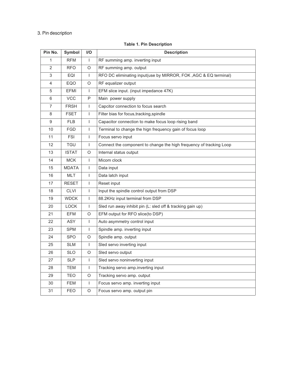
Table 1. Pin Description
Pin No. Symbol I/O Description
1 RFM I RF summing amp. inverting input
2 RFO O RF summing amp. output
3 EQI I RFO DC eliminating input(use by MIRROR, FOK ,AGC & EQ terminal)
4 EQO O RF equalizer output
5 EFMI I EFM slice input. (input impedance 47K)
6 VCC P Main power supply
7 FRSH I Capcitor connection to focus search
8 FSET I Filter bias for focus,tracking,spindle
9 FLB I Capacitor connection to make focus loop rising band
10 FGD I Terminal to change the hign frequency gain of focus loop
11 FSI I Focus servo input
12 TGU I Connect the component to change the high frequency of tracking Loop
13 ISTAT O Internal status output
14 MCK I Micom clock
15 MDATA I Data input
16 MLT I Data latch input
17 RESET I Reset input
18 CLVI I Input the spindle control output from DSP
19 WDCK I 88.2KHz input terminal from DSP
20 LOCK I Sled run away inhibit pin (L: sled off & tracking gain up)
21 EFM O EFM output for RFO slice(to DSP)
22 ASY I Auto asymmetry control input
23 SPM I Spindle amp. inverting input
24 SPO O Spindle amp. output
25 SLM I Sled servo inverting input
26 SLO O Sled servo output
27 SLP I Sled servo noninverting input
28 TEM I Tracking servo amp.inverting input
29 TEO O Tracking servo amp. output
30 FEM I Focus servo amp. inverting input
31 FEO O Focus servo amp. output pin
3. Pin description

 Loading...