EasyManua.ls Logo

JVC PC-X95B User Manual

JVC PC-X95B
44 pages
To Next Page IconTo Next Page
Page #1 background imageLoading...
Page #1 background image
JVC
PC-X95pvevcener
SERVICE
MANUAL
Contents
Page
Safety
Precautions
@
Instructions
(Extract)
T]
Location
of
Main
Parts
occ
eeeeesssessessecneeneeseens
15
|
Removal
of
Main
Parts
.....
ce
eeeeeeeccseeeseceseesseeseenes
16
Receiver
SECTION
.......ccecccceccceesececetneceeeersteneeeeessaees
16
Cassette
Mechanism
Section
0.0.0.0...
19
[3].
Main
Adjustment
oo...
cece
ce
ceteseeeerteeteretenreeens
20
[4]
Wiring
Connection
«oo...
cesses
eesti
25
5]
Standard
Schematic
Diagram
ou...
cece
26
Amplifier
Circuit
.........ccccccccccesessesenstereceteeaseseerteeees
CD
Amplifier
Circuit...
eccececseseseeeeeeeeeeeeienes
CD
Control/Tuner
Circuit
SI
[ol]
[o
)
isc
DIGITAL
AUDIO
Area
Suffix
Continental
Europe
Germany
Northern
Europe
Page
Block
Diagrams...
ose
ie
lee
eeneeeet
29
Location
of
P.
C.
Board
and
Parts
List
.....
30
Main:
Board
occ
iieliliiecicdsiesssievapeseset
CD:
Amplifier
Board
oo...
cece
cia
cesiceeeeesestsees
CD
Controller
Board
oo...
eceeceeereeens
Exploded
View
of
Enclosure
.
ReCeIVEr
SECTION
ooo.
eececeeceesscescsseceeseseseeeeeceerernernes
Speaker
Box
Section
ooo...
eeccecceeeeetereneerereeteeee
Exploded
View
of
Mechanism
............::cceecceceeeeeeeee
40
Cassette
Mechanism
...........cccccseessseccesssneeeeeeeerees
40
CD
Mechanism
.
PACKING:
2.esesues
oie
es
ect
eianies
ede
howetns
No.
1859
June
1992
Question and Answer IconNeed help?

Do you have a question about the JVC PC-X95B and is the answer not in the manual?

JVC PC-X95B Specifications

General IconGeneral
BrandJVC
ModelPC-X95B
CategoryCD Player
LanguageEnglish

Summary

Safety Precautions

Important Management Points Regarding Safety

Laser Product Safety

Precautions for Class 1 laser products, including warnings and safe handling.

Instructions (Extract)

Names of Parts and Their Functions

Top Panel Components

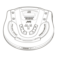
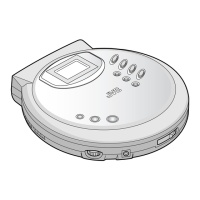
Identification and function of parts located on the top panel of the device.

Playing Compact Discs

Skip Playback

Search Playback

How to use fast-forward or reverse search to find positions on a disc.

Stopping Playback

Procedures for stopping disc playback or pausing temporarily.

Programmed Playback

Clearing Programmed Tunes

Instructions for clearing programmed track selections from memory.

Repeat Playback

How to set the unit to repeat single tunes or all tunes.

Cassette Playback

Relay Playback

How to play tapes sequentially from deck B to deck A.

Radio Reception

Synchronized Recording with CD Player

Dubbing (Synchro Start Dubbing)

Erasing Tapes

Procedure for erasing tape content before recording new material.

Troubleshooting

Location of Main Parts

Removal of Main Parts

Receiver Section Removal

Steps to remove the front cabinet and receiver section components.

Cassette Mechanism Assembly Removal

Procedure for removing the cassette mechanism assembly and its connections.

CD Unit Disassembly

Steps for disassembling the CD player unit.

Pickup Replacement

Steps for removing and replacing the CD pickup assembly.

Reassembly of Tuner Section

Instructions for correctly reassembling the tuner section components.

Cassette Mechanism Component Removals

Detailed breakdown and removal of cassette mechanism parts.

Main Adjustment

CD Player Adjustment

Procedures for adjusting the CD player for optimal performance.

Maintenance of CD Pickup

Tracking Offset Adjustment

How to adjust the tracking error signal for proper disc playback.

Tuner Alignment

AM IF Alignment

Steps for aligning the AM intermediate frequency circuit.

FM IF Alignment

Steps for aligning the FM intermediate frequency circuit.

MW RF Alignment

Deck Adjustment

Wiring Connection Diagram

Standard Schematic Diagram

Amplifier Circuit Schematic

Overall schematic diagram of the amplifier circuit board.

CD Amplifier Circuit Schematic

Schematic diagram detailing the CD amplifier circuit.

CD Control and Tuner Circuit Schematics

Schematic diagrams for the CD control and tuner circuits.

Block Diagram

Tuner Section Block Diagram

Block diagram illustrating the functional flow of the tuner section.

CD Section Block Diagram

Block diagram illustrating the functional flow of the CD player section.

Amplifier Section Block Diagram

Block diagram illustrating the functional flow of the amplifier section.

Location of P. C. Board and Parts List

Main Board Identification

Diagram showing the layout and parts on the main printed circuit board.

Main Board Parts List

Comprehensive list of components and their specifications for the main board.

CD Amplifier Board

CD Amplifier Board Parts List

Detailed list of components and their specifications for the CD amplifier board.

CD Controller Board

CD Controller Board Parts List

Detailed list of components and their specifications for the CD controller board.

Exploded View of Enclosure

Receiver Section Enclosure

Exploded view illustrating the assembly of the receiver section enclosure.

Enclosure Parts List

List of parts required for the external enclosure of the unit.

Speaker Box Section

Speaker Box Parts List

List of parts for the speaker box assembly.

Exploded View of Mechanism

Cassette Mechanism Exploded View

Exploded view showing the assembly of the cassette mechanism.

Cassette Mechanism Parts List

Detailed list of parts for the cassette mechanism.

CD Mechanism

CD Mechanism Parts List

Detailed list of parts for the CD mechanism assembly.

Packing

Packing Parts List

List of parts and items included in the product packaging.

Related product manuals