RC-BM5
1-24
Pin No. I/O FunctionSymbol
50
51
52
53
54
55
56
57
58
59
60
61
62
63
64
V
SSD2
DOBM
V
DDD1(P)
CFLG
RA
FO
SL
V
DDD2(C)
V
SSD3
MOTO1
MOTO2
V4
V5
V1
LDON
-
O
-
O
O
O
O
-
-
O
O
O
O
I
O
Digital ground 2
Bi-phase mark output (externally buffered;3-state)
Digital supply voltage 1 for periphery
Correction flag output (open-drain)
Radial actuator output
Focus actuator output
Sledge control output
Digital supply voltage 2 for core
Digital ground 3
Motor output 1;versatile (3-state)
Motor output 2;versatile (3-state)
Versatile output 4
Versatile output 5
Versatile input 1
Laser drive on output (open-drain)
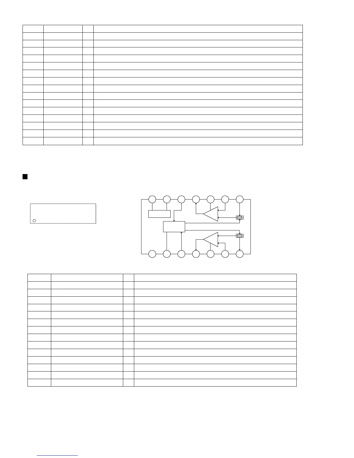
AN7312 (IC601) : Dual recording/Playback pre-amplifier circuit with ALC
1. Terminal layout
3. Pin function
2. Block diagram
17
~
14 8
~
1
2
3
4
5
6
7
8
9
10
11
12
13
14
GND
ALC time constant
ALC input Ch.1
Output Ch.1
Phase compensation Ch.1
N.E.B. Ch.1
Input Ch.1
Input Ch.2
N.E.B. Ch.2
Phase compensation Ch.2
Output Ch.2
ALC input Ch.2
Ripple filter
Vcc
GND
ALC time constant by resistance and capacitor
Right channel ALC input
Right channel output
Not connect
Right channel negative feed back input
Right channel signal input
Left channel signal input
Left channel negative feed back input
Not connect
Left channel output
Left channel ALC input
Ripple filter
Power supply
Pin No. Symbol Function
-
-
I
O
-
I
I
I
I
-
O
I
-
-
I/O
14 13 12 11 10
9
1 2 3 4 5 6
Ripple Filter
Amp.
Ch2
8
ALC
7
GND
Vcc
Amp.
Ch1

 Loading...