EasyManuals Logo
Home>JVC>CD Player>RC-BM5

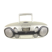
JVC RC-BM5 Service Manual

JVC RC-BM5
52 pages
To Next Page IconTo Next Page
To Previous Page IconTo Previous Page
Page #25 background imageLoading...
Page #25 background image
RC-BM5
1-25
1
2
3
4
5
6
7
8
9
10
11
12
13
14
15
16
17
18
19
20
40
39
38
37
36
35
34
33
32
31
30
29
28
27
26
25
24
23
22
21
1.Terminal layout
3.Pin function
MX10FLCDPC (IC301) : MCU
P1.0 to P1.7
P2.0 to P2.5,P3.4 to P3.5
P0.0 to P0.7
P3.3
P2.7
ALE
EA
P3.7,P3.1,P3.0
VDD
GND
Pin No.
Symbol I/O
A0 to A7
A8 to A13,A14 to A15
Q0 to Q7
CE
OE
WE
Vpp
MS2 to MS0
VDD
GND
I
I
I/O
I
I/O
I
-
-
-
-
Input low order address bits
Input high order address bits
Data input/output
Chip enable input
Output enable input
Write enable input
Program supply voltage, 12.5-13volts
Flash mode selection
Power supply voltage (+5V)
Ground pin
Function
2. Block diagram
PORT 0
DRIVERS
PORT2
DRIVERS
RAM
PORT 0
LATCH
PORT 2
LATCH
ROM
ACC
B
REGISTER
TMP2 TMP1
PSW
STACK
POINTER
T0/T1/T2
SFRs
TIMERS
PORT1
LATCH
osc
PORT1
LATCH
PORT1
DRIVERS
DPTR
PROGRAM
COUNTER
PC
INCREMENTER
BUFFER
RAM ADDR.
REGISTER
P0.0-P0.7 P2.0-P2.7
ALU
TIMING
AND
CONTROL
INSTRUCTION
REGISTER
P3.0-P3.7P1.0-P1.7
XTAL2XTAL1
RST
EA
ALE
PSEN
Vcc
Vss
PROGRAM
ADDR.
REGISTER
T3
WATCHDOG
TIMER
PORT1
DRIVERS

Other manuals for JVC RC-BM5

Questions and Answers:

Question and Answer IconNeed help?

Do you have a question about the JVC RC-BM5 and is the answer not in the manual?

JVC RC-BM5 Specifications

General IconGeneral
BrandJVC
ModelRC-BM5
CategoryCD Player
LanguageEnglish

Related product manuals