(No.MB479)1-15
3.1.20 Removing the DSP connect board
(See Fig.15)
• Remove the top cover, front video board and volume board.
Disconnect the connector CN602
on the DSP connect board
from the input board in an upward direction.
Note:
When removing the DSP connect board, take care not to break
the claw of the connector on the input board.
Fig.15
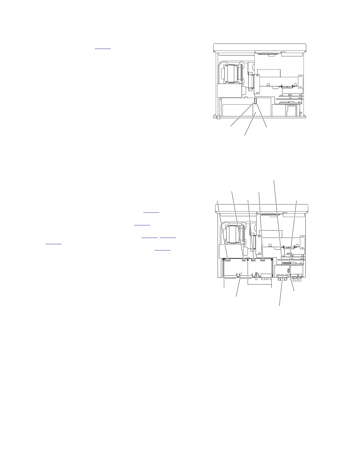
3.1.21 Removing the input board
(See Fig. 16)
• Remove the top cover, rear panel, tuner, subwoofer board,
front video board, compulink board [For Australia], volume
board, OSD board [For Australia], scart board [For Europe]
and DSP connect board.
Reference:
Remove the tie band bundling the wires.
(1) Disconnect the wire from the connector CN209
on the
speaker terminal 2 board.
(2) Disconnect the wire from the connector CN513
on the OSD
connect 1 board.
(3) Disconnect the wires from the connectors (CN530, CN531,
CN552
) on the input board.
(4) Disconnect the parallel wire from the connector CN540 on
the input board.
(5) Remove the three screws X and take out the input board
from the main body.
Fig.16
DSP connect board
Input board
CN602
Input board
Speaker terminal 2 board
CN209
CN552
CN540
CN530
CN531
CN513
OSD connect 1 board
X
X

 Loading...


