1-8 (No.MB479)
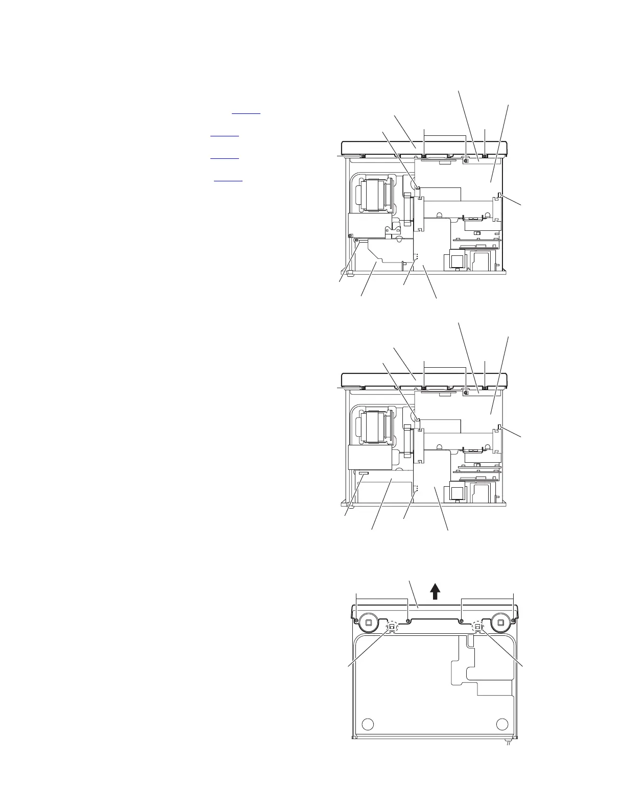
3.1.2 Removing the front panel assembly
(See Figs.3 and 4)
• Remove the top cover.
Reference:
Remove the tie bands and wire holder bundling the wires.
(1) Disconnect the card wire from the connector CN102
on the
main amplifier board. (See Fig.3)
(2) Disconnect the wire from the connector CN351
on the main
amplifier board. (See Fig.3)
(3) Disconnect the wire from the connector CN552
on the input
board. (See Fig.3)
(4) Disconnect the wire from the connector CN661
on the vol-
ume board. (See Fig.3)
(5) Remove the three screws D attaching the front panel as-
sembly. (See Fig.3)
(6) Remove the screw D attaching the OSD connect 2 board.
(See Fig.3)
(7) From the bottom side of the main body, remove the four
screws E attaching the front panel assembly. (See Fig.4)
(8) Release the joints a and remove the front panel assembly
in the direction of the arrow. (See Fig.4)
Fig.3
Fig.4
D
Front panel assembly
D
D
OSD connect 2 board
Main amplifier board
CN351
Volume board
CN552
Input board
CN661
[For Australia]
[For Europe]
D
Front panel assembly
D
D
OSD connect 2 board
Main amplifier board
CN351
Volume board
CN552
Input board
CN661
CN102
CN102
E
Front panel assembly
E
a
a
 Loading...


