13
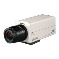
4 Set the switch (A Page 17、 18)
Configure the setting switch and machine ID switch
according to the system.
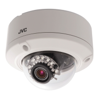
5 Mount the safety wire that connects the ceiling
clamping bracket to the ceiling
Memo :
● The wire should be insulated from the ceiling structure. If
the ceiling structure is metal and insulation is not provided
between the camera and the ceiling structure, image
noise may occur.
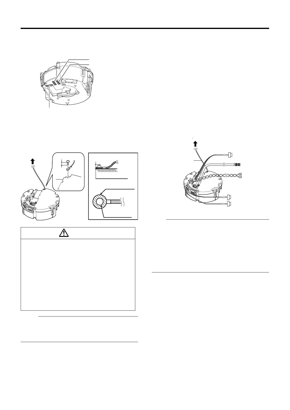
6 Connect the cable (A 20 to 23)
Connect cables to the terminal of the ceiling clamping
bracket.
The connection cables consist of the alarm signal cable,
coaxial cable, control signal cable and AC24V power cable.
A Provided alarm cable (A Page 20)
This connects to devices with alarm input/output
terminals.
B Coaxial cable (A Page 21)
This connects to monitors.
C Power cable (A Page 23)
This connects to AC24V power.
D Alarm signal cable (A Page 20)
This connects to devices with alarm input/output
terminals.
E Control signal cable (A Page 22)
This connects to RM-P2580.
Note :
● Do not connect an AC 24 V cable to AC 230 V power
supply. The camera will be damaged. If the wrong cable is
connected, the internal circuit may be damaged. Do not
use the camera. Bring it to your nearest JVC dealer for
inspection.
● For safety reasons, turn on the power only after all the
connection is complete.
● To supply AC 24 V, use a AC 24 V supplying power unit
that is insulated from AC 230 V line.
● Take note of the length, strength, pull and material
(insulation) of the fall prevention wire and use one with
a wire strength of more than 20 kg.
● The inner diameter of the ring section of the fall
prevention wire mounted on the camera should be R4
mm to R5.5 mm and the outer diameter be R9 mm and
below.
● The thickness of the screw head and the fall
prevention wire (including the washer) should be 6 mm
and below. If it is more than 6 mm, the screw will touch
the ceiling and the camera cannot be installed
horizontally.
● Use M4 fixing screws.
Machine ID switch
No setting
T Set all to AOFFB
Setting Switch
6mm
6 mm and below
R9 mm and below
R4 mm to R5.5 mm
and below
Caution
A
B
C
D
6
Alarm signal cable
Power cable
Control signal cable
Coaxial cable
Safety wire
Provided alarm cable
TK-C686E_EN.book Page 13 Tuesday, December 4, 2007 4:45 PM

 Loading...