1-10
UX-T77
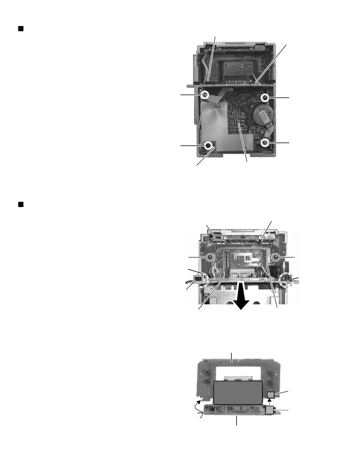
Removing the cassette mechanism unit
(See Fig. 14)
1. Remove the rear panel.
2. Remove the left and right side panels.
3. Remove the CD player unit.
4. Remove the power amplifier board.
5. Remove the front panel assembly.
6. From inside the front panel assembly, remove the four
screws J and K retaining the cassette mechanism
unit.
7. From the connector CN33 on the head amplifier and
mechanism control board, disconnect the card wire
outgoing from the connector CN731 on the LCD
system CPU board.
Removing the function switch board
and LCD system CPU board
(See Fig. 15 and 16)
1. Remove the rear panel.
2. Remove the left and right side panels.
3. Remove the CD player unit.
4. Remove the front panel assembly.
5. Remove the cassette mechanism unit.
6. From inside the front panel assembly remove the two
screws L retaining the operating switch board.
7. From the connector CN782 on the LCD system CPU
board, disconnect the connector wire outgoing from
the connector CN802 on the operating switch board.
8. While sliding the two engagements e fixing the LCD
system CPU board, pull out this board.
9. After disconnect the connector CN801 on the function
switch board from the connector CN781 on the LCD
system CPU board, remove the respective boards
while pulling them upward.
CN731
LCD system
CPU board
K
K
J
J
Cassette
mechanism unit
Head amplifier & mechanism
control board
Fig. 14
LL
e
e
CN802
Operating
switch board
CN782
LCD system
CPU board
Function switch
board
Fig. 15
Fig. 16
LCD system CPU board
CN781
CN801
Function switch board