1-9
UX-T77
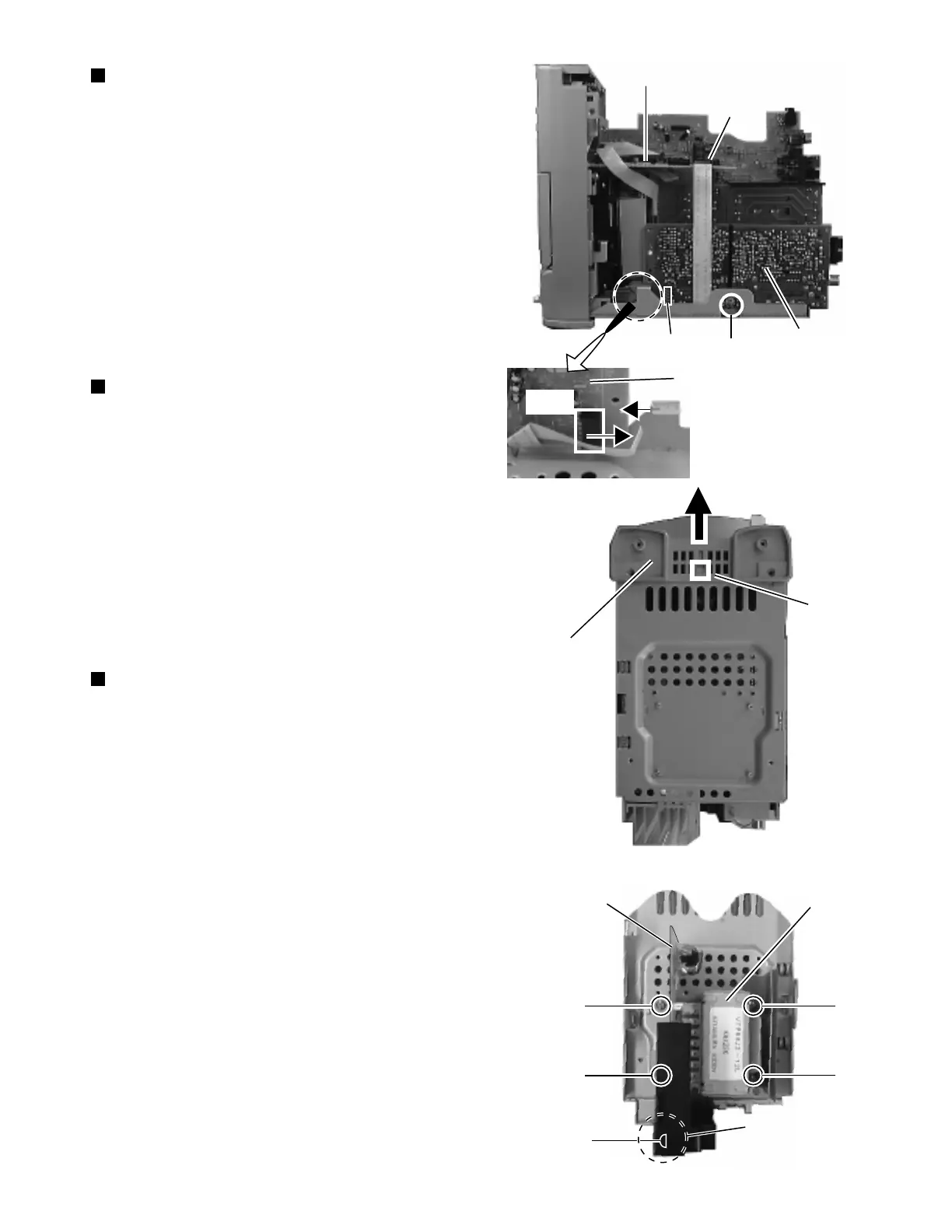
Removing the tuner board (See Fig. 11)
1. Remove the rear panel.
2. Remove the left and right side panels.
3. Remove the CD player unit.
4. From the right side of the body, remove the one screw
G retaining the tuner board.
5. From the connector CN1 on the tuner board, disconnect
the card wire outgoing from the connector CN701 on
the LCD system CPU board. (Fig.11a)
Removing the front panel assembly
(See Fig. 12)
1. Remove the rear panel.
2. Remove the left and right side panels.
3. Remove the CD player unit.
4. Remove the power amplifier board and heat sink.
5. From the bottom of the body, disengage the engagement
d fixing the front panel assembly in Fig. 12 while
pressing in with a minus screw driver, eta.
Removing the power transformer and
power supply board (See Fig. 13)
1. Remove the rear panel.
2. Remove the left and right side panels.
3. Remove the CD player unit.
4. Remove the power amplifier board and heat sink.
5. Remove the tuner board.
6. Remove the four screws H retaining the power
transformer and power supply board and the one screw
I retaining the jack holder.
LCD system CPU board
CN701
Tuner board
G
CN1
Tuner board
Fig. 11
Fig. 12
Fig. 13
Fig. 11a
d
Front panel
assembly
H
H
H
H
I
CN1
Power supply
board
Power
transformer
Jack holder