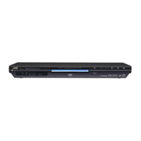
XV-N5SL
33
5.6 MN101C57DLR(IC1):System controller
5.6.1 Pin function
Pin No. Symbol I/O Description
1 VLC1 - LCD Power supply terminal 1 (B5V)
2 VLC2 - LCD Power supply terminal 2 (B5V divide voltage)
3 VLC3 - LCD Power supply terminal 3 (B5V divide voltage)
4,5 NC - Non connect
6 P.ON O Indicator control signal output for STANDBY
7 PRORED O Indicator control signal output for PROGRESSIVE (red)
8 PROGRN O Indicator control signal output for PROGRESSIVE (green)
9 DVDAUDIO O Indicator control signal output for DVD AUDIO
10 N5/NA7 O Indicator control signal output for PLAY
11 VSS - Connect to ground
12,13 OSC1,2 I/O System clock signal oscillation terminal
14 MMOD I Memory enhancing switching
15 XI - Connect to ground
16 XO - Non connect
17 VDD - Power supply terminal (B5V)
18 NRST I Reset input
19 VDD - Power supply terminal (B5V)
20 TXD O Serial transmission data output
21 RXD I Serial receive data input
22 SCK I Serial communication clock input
23 INT O Serial transmission interrupt output
24 CLP O RGB/CMP switching signal output
25 AVCO O AV Compulink output terminal
26 AVCI I AV Compulink input terminal
27 BL O LCD Back lamp drive signal output
28 TCLOSE O Tray open signal output
29 TOPEN O Tray close signal output
30 LMMUTE O 4 ch driver MUTE signal output L:MUTE
31 DISCSET I Disc catch status input H:SET
32 DISCSTP I Disc stop status input H:STOP
33 SWOPEN I Tray open status input H:OPEN L:CLOSE
34 SWUPDN I Tray close status input L:OPEN H:CLOSE
35 REMO I Remote control signal input
36 RGB I RGB/ S video switch signal input
37 CS I Serial receive chip select input
38 POWERSW I Power button input
39 VDD - Power supply terminal (B5V)
40 VREF+ - Power supply terminal (B5V)
41 KEYI0 I Key control signal input 0
42 KEYI1 I Key control signal input 1
43 NTB I NTSC/PAL switch signal input
44 PROINT I INT/PROG switch signal input
45 MUTE O Audio muting output
46 INT/PROG O INT/PROG switch signal output
47 EMODEL O Indicator control signal output for PAUSE
48 CPURST O LSI Reset output
49 VREF- - Connect to ground
50
~96 SEG46~0 O LCD Segment control signal output 46~0
97
~100 COM0~3 O LCD Common signal output 0~3

 Loading...