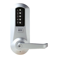
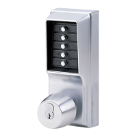
4
2. ADJUSTING THE DRIVE HUB
The drive hub must be adjusted so the following actions occur.
- When the correct buttons of the combination have been depressed, the turn
knob must rotate 90° to the right (clockwise) to the stop position without
restriction.
- When the turn knob is at the 90° position (vertical), the exit device latch
should be completely retracted and the combination buttons will have
automatically reactivated for the next entry.
DDeetteerrmmiinnee tthhee pprrooppeerr sseettttiinngg::
1) In order to determine the proper setting for the exit device being used, insert
a flat bladed screwdriver into the horizontal slot of the exit device hub.
2) Rotate the screwdriver to the right (clockwise) until the exit device latch is
fully retracted. Note the position of the screwdriver (45º, 60º, or 90º). Once
your setting has been determined, adjust the drive hub (if necessary) as
described below.
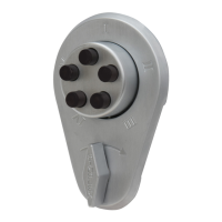
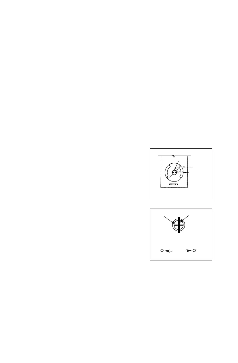
The factory setting of the drive hub is shown in Figures 2-1 and 2-2.
WWhheenn 4455°° aaccttiivvaattiioonn ooff ddrriivvee hhuubb iiss rreeqquuiirreedd ttoo ffuullllyy
rreettrraacctt tthhee eexxiitt ddeevviiccee llaattcchh aanndd 4455°° ffrreeee ttrraavveell ooff
tthhee ccoonnnneeccttiinngg bbaarr iiss nneecceessssaarryy
, leave the drive hub
at the factory setting as shown in Figure 2-1.
The connecting bar should enter the hub of the exit
device horizontally as shown in Figure 2-2.
CCaamm AAddjjuussttmmeenntt SStteeppss ((wwhheenn nneecceessssaarryy))
Using the Allen wrench supplied (
5
⁄64 x 1
31
⁄32), adjust
the drive hub as follows:
1) Loosen the three Allen set screws and rotate
the drive hub to achieve the setting as shown,
then secure the drive hub by tightening the
three Allen set screws. One screw must align
with the groove of the shaft.
It may be necessary to twist the end of the
connecting bar slightly to get a complete latch
retraction of the exit device.
Figure 2-1.
Shaft
Drive hub
Allen screw
Combination chamber
Connecting bar
Pin
Mounting bracket
(back plate assembly
Figure 2-2.
Back view of front lock assembly
Mounting
screws