3
1. PREPARING FOR INSTALLATION
The 2015 is designed to operate surface-mounted rim style exit devices, with a
maximum hub rotation of 90° clockwise, which is required to fully retract the exit
device latch. The 2015 replaces most key cylinders on new or existing exit
devices.
A standard pull can be mounted below the 2015 to pull the door open.
The 2015 cannot be used with thumb operated, mortise design, or vertical rod
devices.
The 2015 can be installed on wood or metal doors measuring 1
3
⁄8" (35 mm) to
2
1
⁄2" (64 mm) thick with a minimum stile (the width of clear mounting surface)
of 3
1
⁄8
" (79 mm). The exit device used should have a minimum backset of 1
9
⁄16"
(40 mm).
Backset is the distance from the center of the key cylinder hole to the
edge of the door
.
The exit device can be locked in the unlocked position “dogged” without affecting
the operation of the 2015.
IIMMPPOORRTTAANNTT
: To install the 2015 with an existing exit device
tthhaatt iiss ccoonnttrroolllleedd
wwiitthh aann oouuttssiiddee kkeeyy ccyylliinnddeerr
start at Step 1.
To install the 2015 with an existing exit device
tthhaatt iiss nnoott
ccoonnttrroolllleedd wwiitthh aann oouuttssiiddee kkeeyy ccyylliinnddeerr
, drill a hole through the
door to align with the exit device hub. The hole should be a
minimum of
3
⁄4" (19 mm) to a maximum of 1
3
⁄8" (35 mm). Start
the installation at Step 2.
IInnssttaallllaattiioonn SStteeppss
1) Remove the existing key cylinder from the door to expose the through hole
to the exit device hub (see Figure 1-1).
The diameter of this hole should be a minimum of
3
⁄4" (19 mm) to a maximum
of 1
3
⁄8" (35 mm).
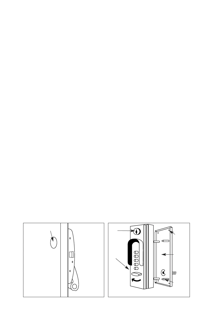
2) Insert the control key into the 2015 lock and turn it 90° to the right
(clockwise) to the horizontal position.
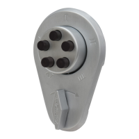
3) Pull the front lock assembly from the mounting bracket (see Figure 1-2).
Figure 1-2.
Front lock
assembly
Control key
insert
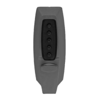
Figure 1-1.
Mounting
bracket
Through hole to
exit device hub
Mounting
screws
Lock-in
studs