6
4. INSTALLING THE LOCK
TThhee ddoooorr mmuusstt bbee ooppeenn..
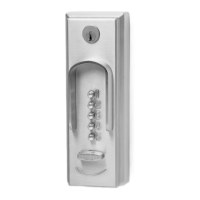
1) Place the mounting bracket against
the outside of the door while aligning
the connecting bar with the operating
hub of the exit device. Refer to the
position of the connecting bar and pin
in Section 2.
2) Hold the mounting bracket against the
door while making certain that the
connecting bar is centered in the exit
device hub and the mounting bracket is
parallel with the vertical edge of the
door. Use the center punch to make
starter holes for the mounting screws
(see Figure 4-1).
NNoottee::
For metal door applications, it is
necessary to drill pilot holes.
If you decide to use thru-bolts to
attach the mounting bracket to the
door, make sure that the thru-bolts do
not interfere with the exit device. You
can drill auxiliary holes in the
mounting bracket to accommodate the
thru-bolts.
3) Fas ten the mounting bracket to the
front surface of the door with the four
sheet metal mounting screws or your
thru-bolts.
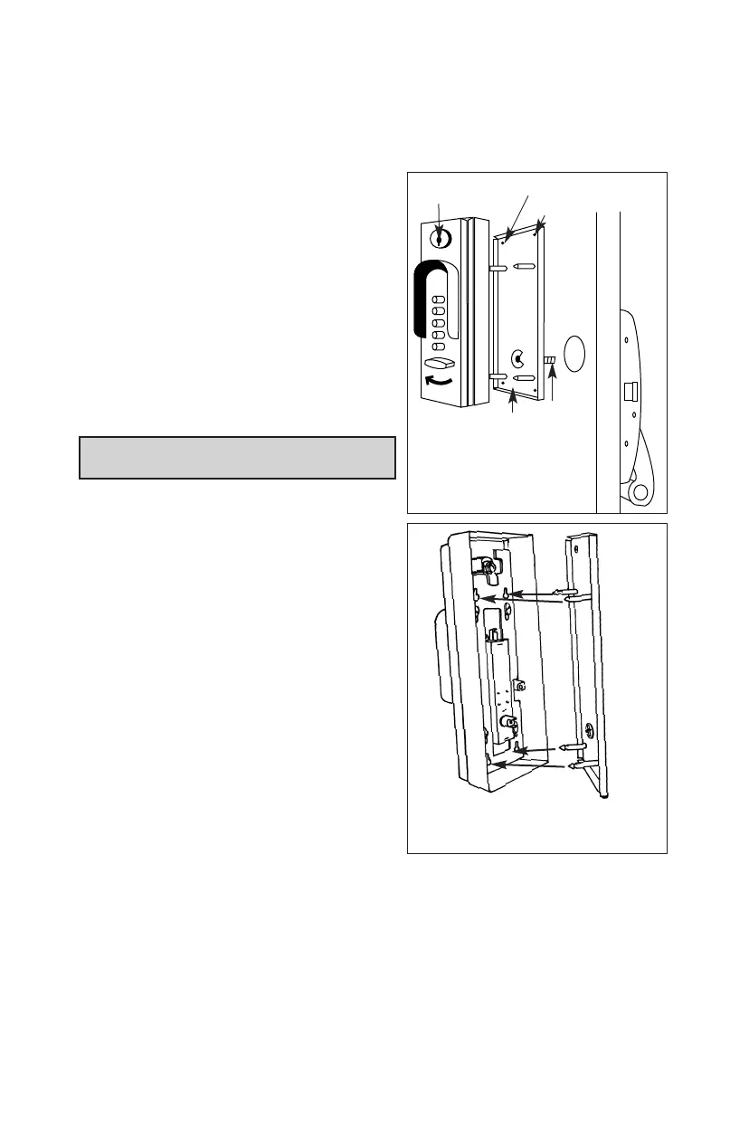
4) The control key must be turned to the
right (clockwise). Align the lock-in
studs of the mounting bracket with the
lock-in plate of the front lock assembly
(see Figure 4-2).
5) Turn the control key to the left
(counterclockwise) to the vertical
position and then remove the key.
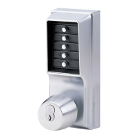
The front lock assembly is now attached and locked to the mounting bracket.
The heavy duty cast metal case is secured to the mounting plate at four
separate points when the six-pin key cylinder is in the locked position.
The front lock assembly must be flush against the door and the pin of the
connecting bar properly located in the drive hub.
6)
BBeeffoorree yyoouu cclloossee tthhee ddoooorr
, check the operation of the lock. Refer to Section
5,
Operating the Lock
.
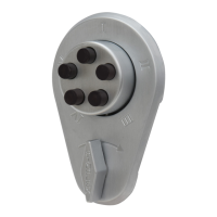
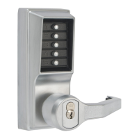
Figure 4-1.
Control key insert
Front lock assembly (front view)
Mounting
s
crews
Mounting
b
racket
Connecting
bar
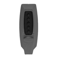
Align lock-in studs
with lock-in plate
Figure 4-2.