5
W
W
h
h
e
e
n
n
9
9
0
0
°
°
f
f
u
u
l
l
l
l
a
a
c
c
t
t
i
i
v
v
a
a
t
t
i
i
o
o
n
n
o
o
f
f
d
d
r
r
i
i
v
v
e
e
h
h
u
u
b
b
i
i
s
s
r
r
e
e
q
q
u
u
i
i
r
r
e
e
d
d
t
t
o
o
f
f
u
u
l
l
l
l
y
y
r
r
e
e
t
t
r
r
a
a
c
c
t
t
t
t
h
h
e
e
e
e
x
x
i
i
t
t
d
d
e
e
v
v
i
i
c
c
e
e
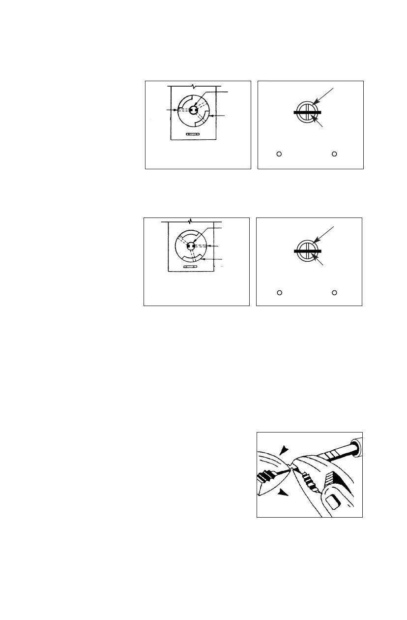
llaattcchh aanndd nnoo ffrreeee ttrraavveell ooff tthhee ccoonnnneeccttiinngg bbaarr iiss nneecceessssaarryy
, set the drive hub
as shown in Figure 2-3.
The connecting bar
should enter the hub of
the exit device vertically
as shown in Figure 2-4.
WWhheenn 6600°° aaccttiivvaattiioonn ooff ddrriivvee hhuubb iiss rreeqquuiirreedd ttoo ffuullllyy rreettrraacctt tthhee eexxiitt ddeevviiccee
llaattcchh aanndd 3300°° ffrreeee ttrraavveell ooff tthhee ccoonnnneeccttiinngg bbaarr iiss nneecceessssaarryy
, set the drive hub
as shown in Figure 2-5.
The connecting bar
should enter the hub
of the exit device
vertically as shown in
Figure 2-6.
You may have to shorten the connecting bar to fit the thickness of your door. See
the instructions in Section 3,
Shortening the Connecting Bar
.
3. SHORTENING THE CONNECTING BAR
The connecting bar is scored in several places so you
can easily break off the section that extends beyond
the required length to engage exit device hub.
1) Hold the connecting bar firmly with a pair of
pliers on the mounting bracket side of the
connecting bar, adjacent to the desired break line.
2) With a second pair of pliers, grip the connecting
bar on the other side of the scored line and
bend up and down until it breaks (see Figure 3-1).
Figure 2-5.
Figure 2-3.
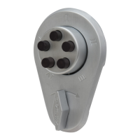
Shaft
Drive
hub
Combination
chamber
A
llen
screw
Shaft
Allen
screw
Combination
chamber
Drive hub
C
onnecting bar
P
in
Connecting bar
Pin
Figure 3-1.
Mounting bracket
(back plate assembly
Mounting bracket
(back plate assembly)
Figure 2-4.
Figure 2-6.