5 Installation and startup
KACO Gerätetechnik GmbH 7 Installation Instructions Powador 01xi
Figure 5.2: Safety catch is open (left) and closed (right)
5.3 Electrical connections
General Information
The electrical connections can be established after the
inverter has been installed in its fixed location.
All applicable safety instructions, technical connections
stipulated by the responsible Electrical Supply
Company, and the relevant VDE regulations must be
adhered to.
To connect the inverter the AC and DC side must be
disconnected from all voltage sources and
protected against inadvertent switching-on.
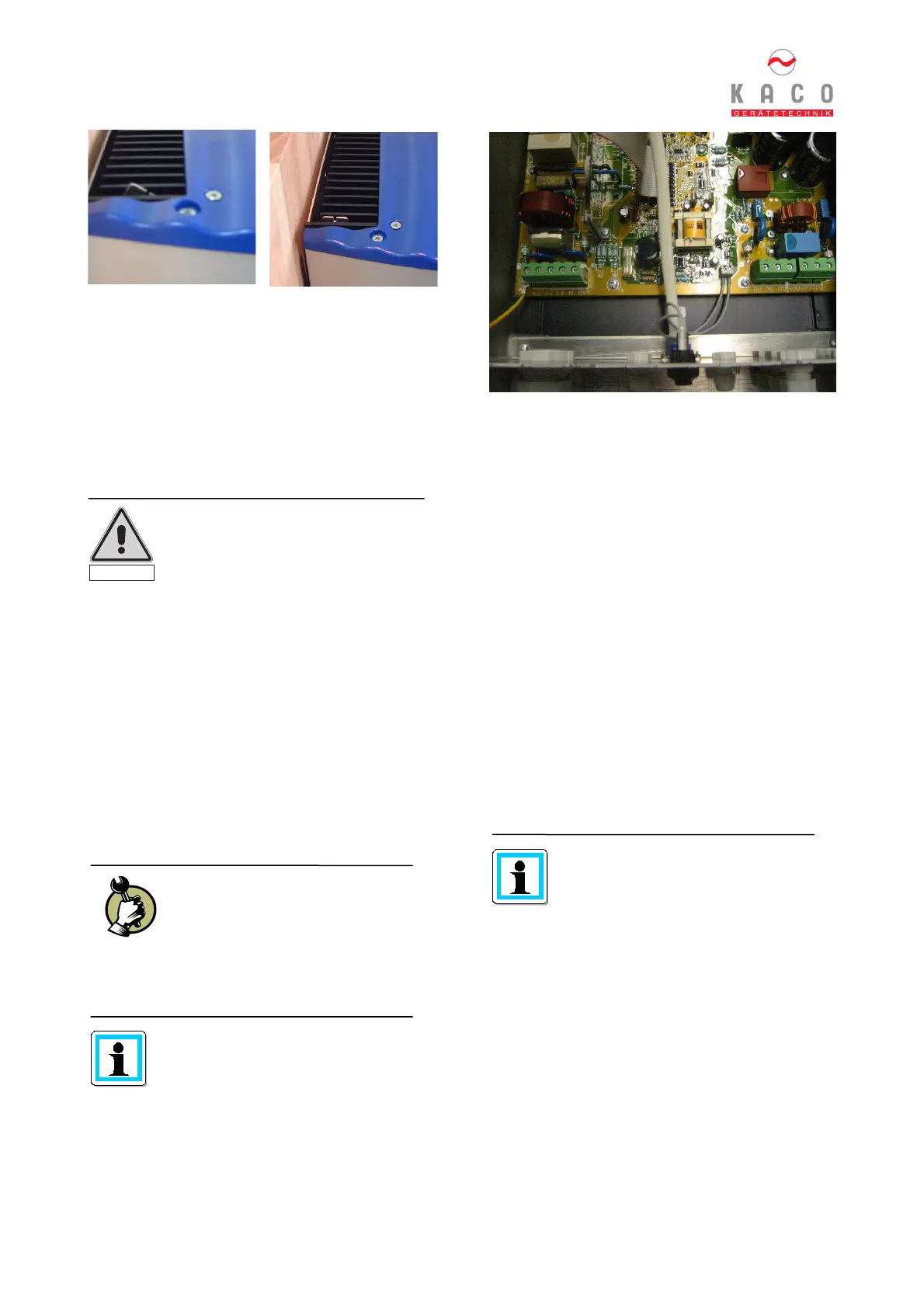
The connection of the PV generator and the grid
connection are established via PCB terminals in the
connection box of the inverter (see Figure 5.3).
Figure 5.3: Connection box of Powador
Grid connections
3-lead connections are used (L1, N, PE). To insert the
wires use watertight conduits at the underside of the
housing.
We recommend the following wire cross sections for
cable lengths up to 20 m:
Powador 1501xi: 1.5 mm
2
Powador 3501xi: 2.5 mm
Powador 4501xi: 6 mm
2
Larger cross sections should be used for longer cable
lengths. According to VDE 0100 Part 430 “Protection of
cables and lines in the event of overcurrent”, NYM
leads should be protected as follows (fixed wiring,
ambient temperature 25 °C and installation type B2
(multi-wire lead in a tube or channel on or inside walls
or buried):
1.5 mm2 16A
2.5 mm2 20A
4 mm2 25A
6 mm2 35A
NEOZED cutout fuses of the type gL should be used as
fuses.
The max. cross section of the AC and
DC terminals is 10 mm².
Caution!
The electrical installation of
Powador must only be performed
by skilled personnel and by an
electrician who has been approved
by the responsible Electrical Utility
Company.
Open the door of the housing/enclosure.
The door is secured against opening by
means of two recessed-head screws on
the right upper side.
Please make sure to use sufficiently
wide wire cross-sections to avoid
excessive line impedance (internal
resistance of the electrical grid)
between the domestic distribution and
the respective Powador inverter.
At a high line impedance, i.e. long AC-
side leads, the voltage at the grid
terminals will increase during power
delivery. This voltage is measured by
the inverter. If the voltage across the
grid terminals exceeds a defined limit,
the inverter will switch off due to grid
overvoltage. This condition must by all
means be taken into consideration for
dimensioning the AC lead.
Caution
 Loading...