4 Operation
KACO Gerätetechnik GmbH 4 Operator’s Instructions Powador
The term „intended use“ shall also include the
adherence to the operating and installation instructions.
Your skilled and authorized electrician will obtain the
necessary applications and acceptance for your
photovoltaic installation from your Utility Company.
Some of the documents which are needed for these
applications and acceptance are attached to these
installation instructions.
4 Operation
The grid-feeding process starts in the morning when
there is enough daylight and, consequently, a certain
minimum voltage is applied to the inverter. After a
startup period of 3 minutes the inverter enables the grid
feeding process. If this minimum voltage is fallen below
at the end of day, the grid feeding process will be
terminated and the inverter will be switched off.
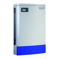
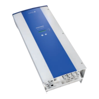
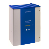
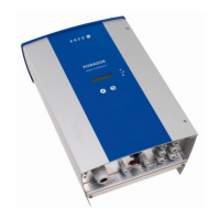
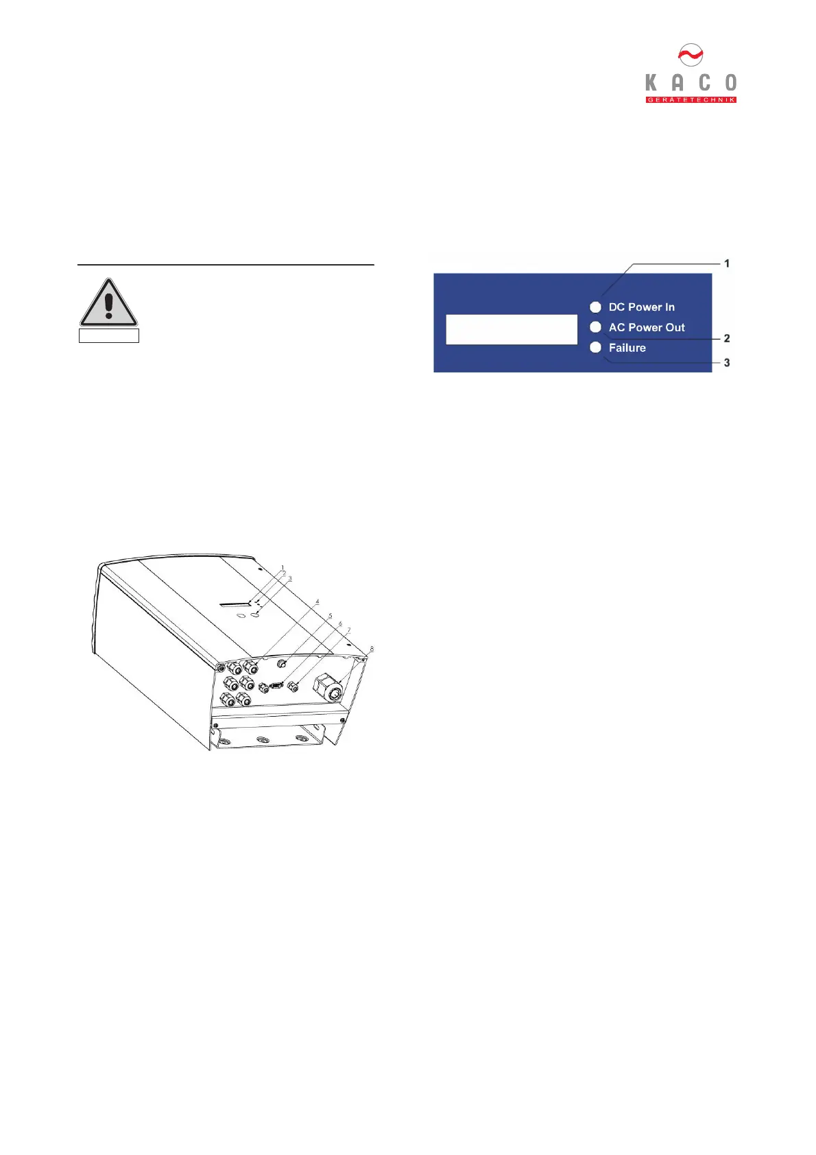
4.1 Overview of operating elements and displays
Figure 4.1: Overview of Powador
Captions
1 Display
Display of measured values and parameter settings
2 LED displays
Display of operating mode
3 Operating keys
Toggle function between measured values and
parameter settings
4 Cable fitting for AC connection
5 Start key
This key is used to activate the display messages at the
end of the day when it is getting dark.
6 RS232 interface
7 Cable duct for RS485 interface cable
8 Cable duct for DC connection
4.2 LED displays
Under normal operating conditions the photovoltaic
modules will start to generate voltage as soon as
enough daylight or sunlight is available. If a certain
amount of voltage is applied to the inverter for a certain
period of time, the inverter will start the grid-feeding
process. The inverter is equipped with three LEDs,
which provide information about the different modes of
operation as follows:
Figure 4.2: LED displays
LED DC Power In (1) (green):
This LED is illuminated from a generator voltage of
approx. 100 V onward and extinguishes as soon as the
generator voltage falls below 80 V. The DC Power In
LED signals that the inverter is in its active state and
the inverter controls are enabled. If this LED is not lit up
the inverter will not be able to start grid feeding. Under
normal operating conditions the LED is illuminated in
the morning when there is enough daylight, and
extinguishes again when it gets dark.
LED AC Power Out (2) (green):
This LED is illuminated during the grid feeding process.
To this effect, the generator voltage must first exceed a
value of 125 V (factory setting) for 3 minutes, ensuring
that the PV generator provides enough power. This
means that the “AC Power Out“ LED is not lit up unless
the PV generator LED is illuminated.
Under normal operating conditions the inverter starts
grid feeding in the morning and terminates this process
as it becomes dark. On cloudy days or during the winter
months the grid feeding process can be interrupted at
certain times, depending on the PV generator and the
actual grid feeding capacity, and can be resumed later
on. This process might be repeated for several times,
especially in the morning and evening. This is not a sign
of faulty operation but is normal operating behavior.
Failure LED (3) (red):
This LED indicates that the grid-feeding process has
been terminated as a result of a malfunction / failure.
The “failure” LED is activated in the following cases:
- Grid overvoltage or low voltage
- Grid frequency error
- Excessive generator voltage
- Excessive generator power
- High-temperature shutdown
- Defective device
Please wait for approx. 10 minutes to verify if the
malfunction only occurs temporarily. If not, please
contact your authorized electrician. On elimination of
the disturbance the grid-feeding process is re-started
after approx. 10 seconds.
Caution!
Using the device for any purposes
other than intended/normal use is
prohibited!
Caution
 Loading...