5. Remove the fitting 4 and replace the air pipe 1 .
6. Make the machine ready for operation, as described in section 10.14.4, or check the air receiv‐
er relief valve.
10.14.2 Checking the air receiver relief valve
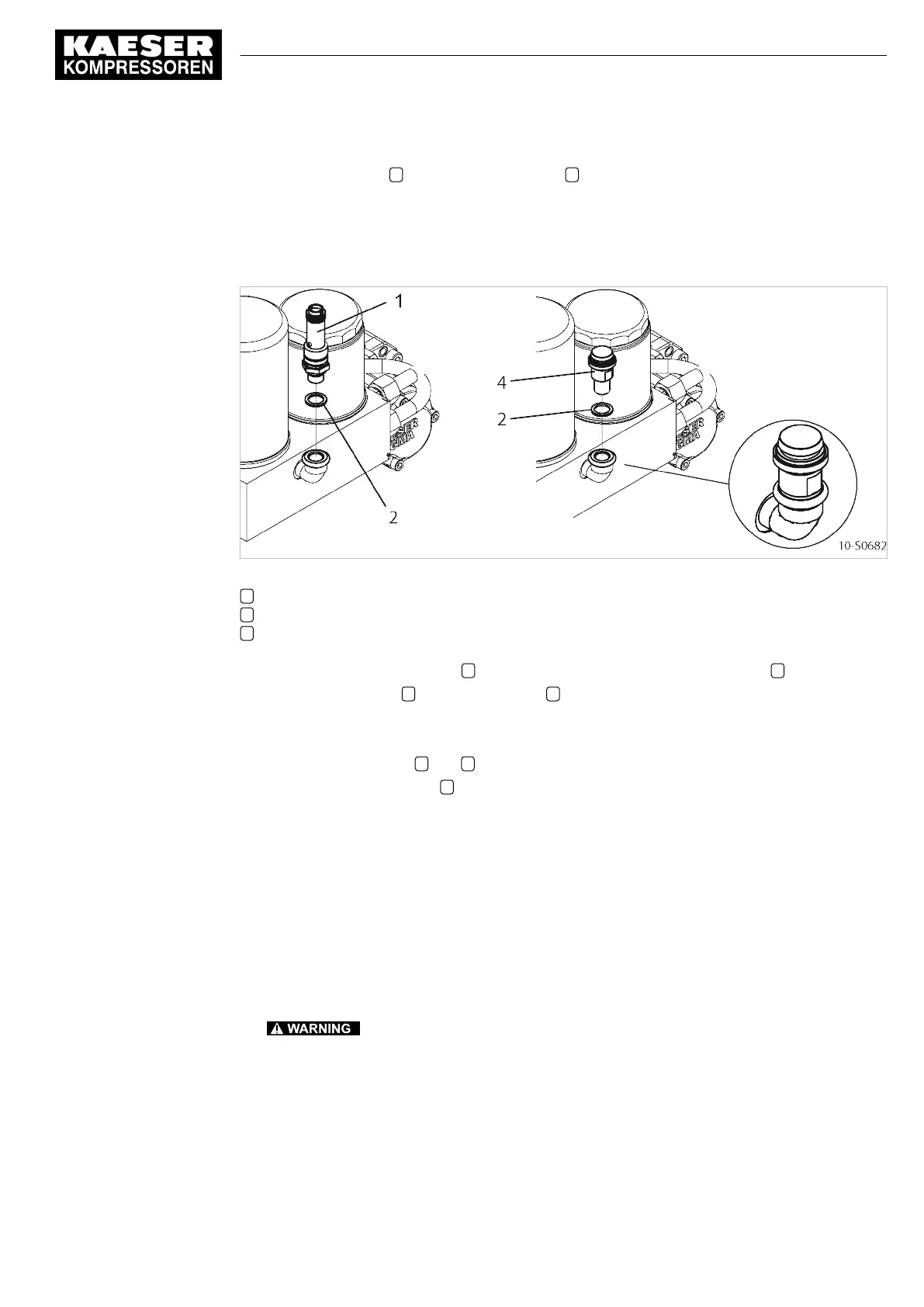
Fig. 29 Air receiver: Testing the safety relief valve
1 Safety relief valve
2 Copper gasket
4 Service fitting
1. Loosen the safety relief valve 1 and remove together with the copper gasket 2 .
2. Fit the service fitting 4 with copper gasket 2 in place of the safety relief valve.
3. Carry out an inspection as described in section 10.14.3.
4. Switch the machine off and depressurize completely.
Both pressure gauges 2 and 9 (Fig. 23) read 0 psig.
5. Remove the service fitting 4 and replace it with the safety relief valve and a new copper gas‐
ket.
6. Make the machine ready for operation again as described in section 10.14.4.
10.14.3 Performing the test
The machine starts and runs under LOAD as long as the «ON» button is held down. Pressure in
the receiver to be checked rises. The time taken until the safety relief valve blows off depends on
the volume of the air receiver. The machine switches to STANDSTILL as soon as the «ON» button
is released.
Precondition The machine is switched off.
1.
The safety relief valve may blow off at any time!
Excessive noise is caused when the safety relief valve blows off!
There is danger of scalding from hot oil.
There is danger of injury from bursting components and compressed air.
➤ Make sure that the enclosure cover is in place.
➤ Wear ear and eye protection.
➤ Abort the test if the working pressure rises 10% above the activating pressure of the valve.
10 Maintenance
10.14 Checking the safety relief valve activating pressure
9_6917 34 USE
Operator Manual Screw Compressor
AIRTOWER 3C–7.5C Tri-Voltage
75
 Loading...


