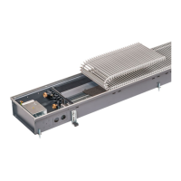
Katherm HK
Assembly, installation and operating instructions
75
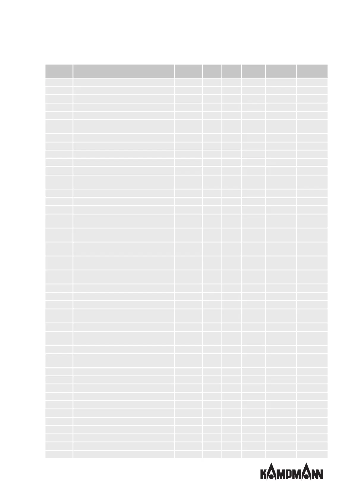
Parameter Function Standard Min. Max. Unit Katherm HK
9
Katherm HK
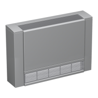
E
10
P030 Ventilation temperature activation 12 0 255 °C 12 12
P031 Ventilation interval 27 0 255 °C 27 27
P032 Rinsing function: maximum idle time of fan 15 0 255 min 15 15
P033 Rinsing function: duration of the rinsing function 120 0 255 s 120 120
P034 Rinsing function: activation in operating modes 0 0 3 - 0 0
P035
Fan run-on time after an operating mode is switched
to stage 1
0 0 255 s 0 0
P036 Type of setpoint setting 0 0 1 - 0 0
P037 Display 1 0 7 - 1 1
P038 Lock/disable function on the control unit 72 0 255 - 72 74
P039 Function of digital output V2 (in a 2-pipe system) 0 0 3 - 0 0
P040 Valve actuation by pulse width modulation 0 0 1 - 0 0
P041
Reset time of PI controller to activate the fan in
automatic fan mode
0 0 20 min 0 0
P042 Fan setting: lock and activate fan stages 0 0 127 - 0
P043 Function of digital input DI1 0 0 22 - 5
P044 Function of digital input DI2 0 0 22 - 0
P045
Threshold voltage for potentiometer to switch on
the unit
10 0 100 kOhm 10 10
P046
Temperature setting corresponds to the minimum
resistance value = 10 kOhm in the potentiometer
18 12 34 °C 18 18
P047
Temperature setting corresponds to the maximum
resistance value = 100 kOhm in the potentiometer
24 13 35 °C 24 24
P048
Threshold voltage for potentiometer for starting up
the fans
10 0 100 kOhm 10 10
P049
Threshold voltage for potentiometer for maximum
fan speed
90 0 100 kOhm 90 90
P050 Fan setting: max. fan speed 100 0 100 % 100 100
P051 Fan setting: min. fan speed 0 0 90 % 15 15
P052 Fan setting: activation of fan speed limit 0 0 1 - 1 1
P053
Valve activation by pulse width modulation of valve
switching cycle
15 10 30 min 15 12
P054 Configuration of bus system 0 0 2 - 0 0
P055
Display of heating/cooling symbols in automatic
mode
0 0 1 - 1 0
P056 DI2 setting (polarity) when DIP 4 = ON 1 0 1 - 1 1
P057
Reset setpoint to the value of P01 (after changing an
operating program)
0 0 1 - 0 0
P058 Sensor calibration: sensor AI1 0 -99 127 K/10 0 0
P059 Supply air temperature setpoint in heating mode 35 0 50 °C 35 35
P060 Supply air temperature setpoint in cooling mode 18 0 50 °C 18 18
P061 Sensor calibration: sensor in the KaController 0 -99 127 K/10 0 0
P062 Sensor calibration: sensor AI2 0 -99 127 K/10 0 0
P063 Outside temperature <P63 fan increase by P122 0 -99 127 °C 0 0
P064 Sensor calibration: sensor AI3 0 -99 127 K/10 0 0
P065 reserved - - - - - -
P066 Master/Slave assignment in CANbus 0 0 1 - 0 0
P067 Serial CAN bus address 1 1 125 - 1 1
P068 Logic of the hydronic algorithms 0 0 7 - 0 0