Deutsch 5.962-786.0 Rev. 05 (06/13) 53
For each valve, the length of a straight pipe with the
same flow resistance is indicated in the following ta-
ble.
Final example:
The pressure loss in a plant with HD 1200 l/h and the
following components is calculated:
Calculation:
100 m = 7.0 bar pressure loss
8.5 m= 0.6 bar pressure loss
108.5 m = 7.60 bar pressure loss
The following table indicates the pressure loss in a
hose line of 10 m length.
Table 5
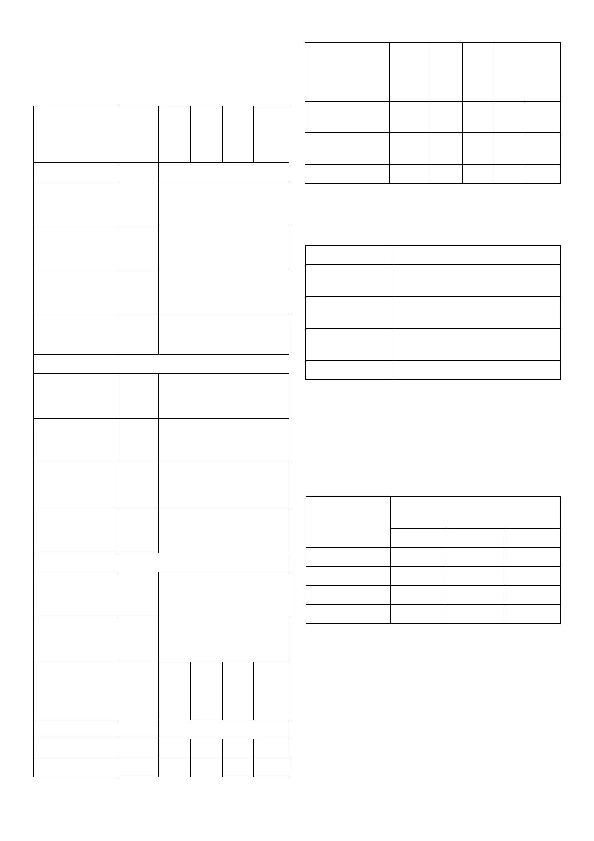
6.4.3 Pressure loss in valves
Valve DN1
0 -
DN1
5
DN2
0 -
DN2
5
DN3
2 -
DN4
0
DN
50
and
more
Bushing 0
Ellbow 90°
r/d = 1.5
0,5
Ellbow 90°
r/d = 2.5
0,3
Double ellbow
wide
1
Double ellbow
narrow
2
T-piece, 90° angle
Tee branch
separation (ex-
traction point)
1,5
T-diameter in-
side
separation
0
T counter direc-
tion
separation
1,3
T counter direc-
tion
merging
3
Tee, streamlined
Tee branch
separation (ex-
traction point)
0,5
T-diameter in-
side
separation
0
DN1
0 -
DN1
5
DN2
0 -
DN2
5
DN3
2 -
DN4
0
DN
50
and
more
Storage 2,5
Knee 2 1,5 1 1
Locking slide 1 0,5 0,3 0,3
Inclined-seat
valve
3,5 3 2,5 2
Full stream
valve
1,5 1 0,5 0,5
DIN stop valve 10 7 5 4
Component corresponds to flow resistance
Pipe DN12,
100 m
100 m
5 extraction
points
2.5 m
3 knee connec-
tions
6 m
HD 1200 l/h Sum 108.5 m
6.4.4 Pressure loss in high-pressure hose lines
Pressure loss
with 10 m hose
[bar]
Water volume [l/h]
750 1000 3000
DN 8 2 4,5 -
DN 10 1,5 2,1 12,5
DN 13 0,2 0,45 3,2
DN 20 - - 0,4
Valve DN1
0 -
DN1
5
DN2
0 -
DN2
5
DN3
2 -
DN4
0
DN
50
and
more
 Loading...