Karel MS48 Installation & Maintenance Guide
Edition 3.2
24
With motherboard only 1 S0 (2 analog lines)
1
st
IA12 ISDN Adaptor
With expansion board 2 S0 (4 analog lines)
With motherboard only 3 S0 (6 analog lines)
2
nd
IA12 ISDN Adaptor
With expansion board 4 S0 (8 analog lines)
3
rd
IA12 ISDN Adaptor With motherboard 5 S0 (10 analog lines)
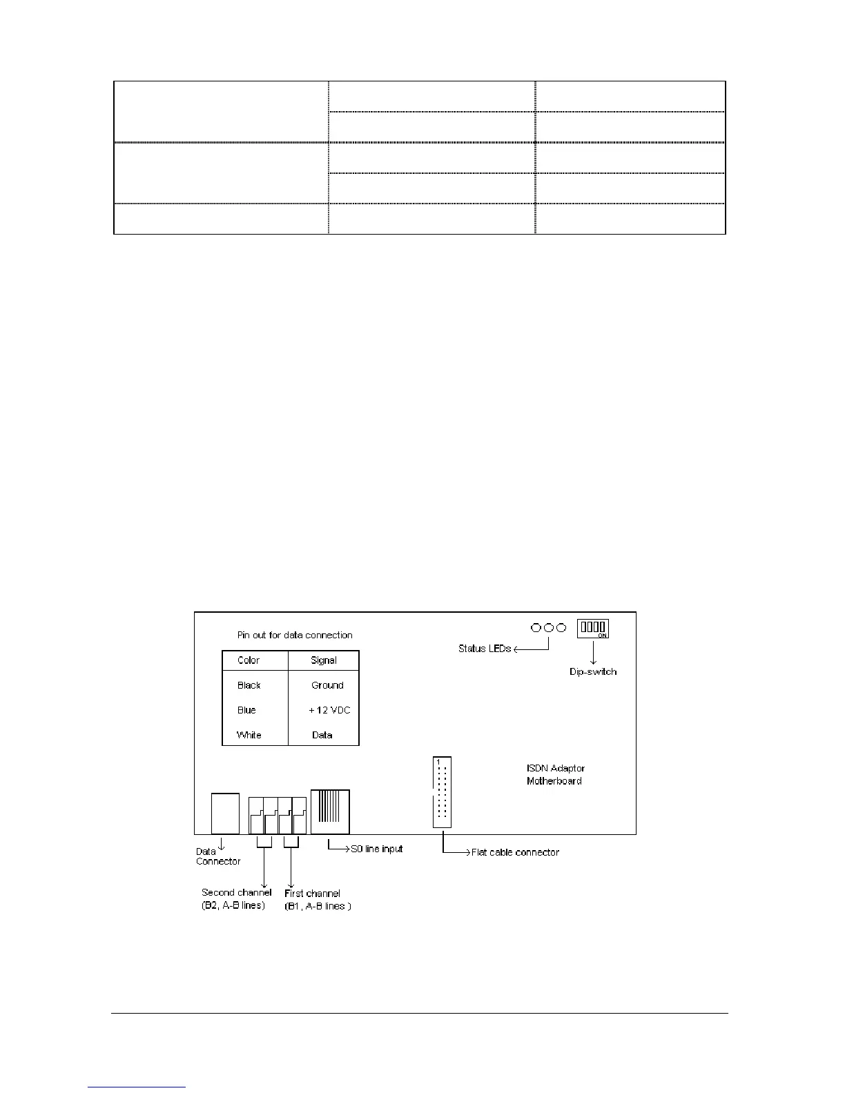
The IA12 motherboard has one 8-pin RJ45 socket for connection to the S0 line
coming from NT1, two 623K4 type connectors for connection to the A / B terminals
of the analog line on the MS48 system and one 6-pin RJ jack for connection to the
data line of KAREL telephones. The data cable having a connection box at one end
and a RJ45 plug at the other end also comes with the adaptor.
The EXP-IA12 Expansion Board has one 8-pin RJ45 socket for connection to the
S0 line coming from NT1 and two 623K4 type connectors for connection to the A /
B terminals of the analog line on the MS48 system. The EXP-IA12 Expansion
Board also comes with a flat cable for IA12 connection, which is to be attached to
the corresponding 20 pin connectors on the IA12 motherboard and EXP-IA12 card.
The IA12 motherboard also has three LEDs to display the status of S0 lines as well
as the data line. The rightmost LED turns on when the adaptor is synchronized with
the S0 line connected to the IA12 motherboard. The middle LED turns on when the
adaptor is synchronized with the S0 line connected to the EXP-IA12 card. And the
leftmost LED turns on when the adaptor is synchronized with the data line.
The outlook of IA12 motherboard and EXP-IA12 card are illustrated in the following
figures.
Figure A-19