Karel MS48 Installation & Maintenance Guide
Edition 3.2
41
III. ACCESSORY INSTALLATION
III.1.
CONSOLES, FEATURE PHONES,
DIRECT STATION SELECT MODULES
• C
ABLING
Each LT48(-H) Feature Phone, OP48(-H) Console and DSS40 / DSS80 Direct
Station Select Module comes with a telephone data cable, which is a 2.5-meter
long cable formed up of two parts. One is a cable with a 6-pin RJ plug at both
ends and the other one is a connection box. The connection box has a 6-pin RJ
socket at one side so that one of the free ends of the cable can be fixed to the
connection box easily. The other free end of the cable has also the
corresponding RJ socket at the backside of the telephone or DSS module.
The system itself also comes with the system data cable
, which is similar to
telephone data cable. One end of the cable is fixed to the connection box. The
other free end of the cable has a 3-pin connector, which is to be inserted to the
CONSOLE connector on the SPS48 card, in order to carry data signals for the
telephones and DSS modules.
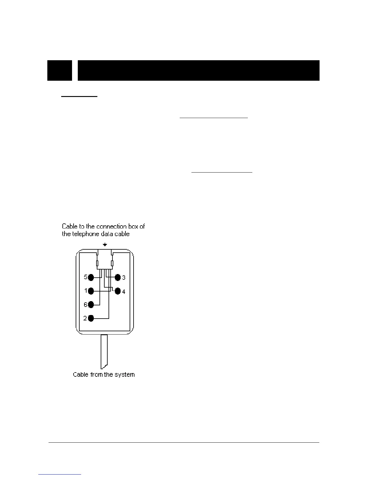
The following signals are present on the connection box of system data cable:
1- Data signal
2- Ground (GND)
3- No connect
4- No connect
5- Busy
6- + 12 VDC
Note : Busy signal is for KY16 Mini Printer.
Figure B-8