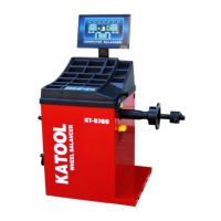
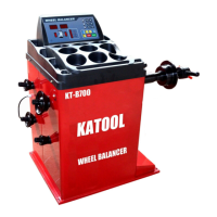
This document describes the Wheel Balancer, a device designed for balancing vehicle wheels.
The wheel balancer offers several key features to ensure accurate and efficient operation:
- Emergency Stop: Equipped with a STOP button for immediate cessation of wheel spinning in emergencies.
- OPT Function: Includes an OPT function to optimize the fit between the tire and the rim.
- Unit Conversion: Features a unit conversion function for flexibility in measurements.
- Multiple Balancing Methods: Provides various balancing methods to choose from, catering to different needs.
- High Accuracy and Speed: Achieves a balancing accuracy of up to ±1g with a short balancing time.
- Self-Correction and Fault Diagnosis: Incorporates self-correction and automatic fault diagnosis functions for reliable operation.
- Balance Decomposition (Hidden Lead): Offers a function to hide balance weights behind spokes for aesthetic purposes.
- Automatic Ruler Ranging and Measuring: Features automatic ruler ranging and measuring capabilities for ease of use.
Technical Data
The technical specifications of the wheel balancer are as follows:
- Maximum Wheel Weight: 65 kg
- Rated Power Supply: 110V or 220V
- Balance Accuracy: ±1g
- Width of Rim: 1.5" – 20"
- Diameter of Rim: 8" – 30"
Control Panel
The control panel features a display and keyboard for operation.
Display Panel Meaning
The display panel provides crucial information during operation:
- No. 1-1 Window: Shows the tire's inboard unbalance value or reference distance A size.
- Window 2-2: Displays the tire's outside unbalance value or diameter D size.
- Window 3-3: Indicates the tire width B dimensions and suggestive characters.
- No. 4-4 Window: Shows the inner side unbalance position (with key indication).
- No. 5-5 Window: Indicates the unbalanced position on the outside (with key indicator on the outside).
- Top Row Lights (1-5): The first five lights indicate the balance mode. The last light is a hidden indicator for unbalanced block segmentation.
- Lights Below Window 7-1: Represent gram and ounce switching instructions.
- Lights Below Window 2: Indicate tire size unit "mm/INCH" switching instructions.
Keyboard
The keyboard consists of several buttons for various functions:
- A Button: Manually enter the reference distance size. Arrows increase/decrease the input size.
- B Button: Manually input size B. Arrows increase/decrease the input size.
- D Button: Manually enter size D. Arrows increase/decrease the input size.
- C Button: Correction key/reset key.
- ALU Button: Selects aluminum ring measurement and dynamic balance measurement.
- D Test Key: Used for balancing machine computer board test.
- OPT Button: Balancing machine optimization function operation key, used for tire rim optimization combination.
- F Button: Static and dynamic balance function switch key.
- FINE Button: Displays actual unbalance value less than 5g (0.3oz).
- mm/inch Button: Switches between mm and inch units for size display.
- Start Button: Initiates operation.
- STOP Button: Emergency STOP and electromagnetic lock button.
Function Conversion Key Combinations
Certain key combinations enable specific functions, which are saved even after shutdown:
- [STOP] + [A↑] + [A↓]: Gram-ounce conversion key.
- [STOP] + [C]: Start under cover.
- [STOP] + [FINE]: Calibration distance measuring ruler A.
- [STOP] + [OPT]: Calibration Diameter Measurement Ruler D.
- [F] + [C]: Machine System Balance Calibration and Set Machine Parameter Values.
- [F] + [START]: Automatic machine aging.
- [D] + [OPT]: Unbalanced decomposition.
Note: Use hand buttons only; avoid using clamps or other sharp objects.
Tire Balance Operation
Power On and Device Code Display
After powering on, the device displays "8.0 5.7 14.0" in the display window, indicating normal operation.
Installation of Wheels
Before testing, ensure proper wheel preparation and installation:
- Preparation: Check and remove dust, soil, metal, stones, or other foreign bodies from the tire and tread. Verify tire pressure is at the specified value. Check for deformation of the positioning surface and mounting hole of the rim, and remove any foreign bodies. Remove the original balance block.
- Installation Types: Three types of wheel installation are available: positive positioning, reverse positioning, and additional flanges for large and medium tires. Choose a method based on the actual situation.
Forward Positioning
This is a common, simple, and fast positioning method suitable for ordinary steel rings and thin aluminum alloy rings, especially when steel ring deformation is present.
- Assembly Order: Spindle - Wheels (rim mounting face inwards) - Fit cone (small head inwards) - Wheels - Quick nut.
Reverse Positioning
Used when the wheel's outside deformation is significant, ensuring accurate positioning of the inner hole and spindle of the steel ring. Suitable for steel rings, especially for measuring thick aluminum alloy.
- Assembly Order: Spindle - Spring - Fit cone (big head inward) - Wheel - Quick nut.
Special Flange Positioning
This method is suitable for tire installation where the wheel center hole is below Φ148.
- Assembly Order: Fix the large flange to the matcher - Wheel - Large cone - Quick nut.
Note: The cone chosen must fit the rim's center hole, and its direction is crucial for accurate measurement.
- Enter Size "A": Use the machine's distance measuring ruler to measure the distance between the balancing machine body and the inner edge of the rim ("A" value).
- Automatic Pull Feet: Pull the pull rod to the '0' bit position, along the pull end, roof, and tire. Stop for a few seconds until three rungs appear on the left display. Retract the pull rod. The left digital tube displays the reference value for input size A, and the right digital tube displays the wheel diameter size D. If values flash, the ruler is not at zero.
- Enter Size "B": Measure rim width "b" with a width caliper. Increase/decrease the value using the corresponding buttons until the measured "B" value is displayed.
- Radar Width Measuring Device: If available, the machine automatically measures width B when the protective cover is lowered, eliminating manual input.
- Enter Size "D": Find the nominal diameter "D" marked on the tire. Increase/decrease the value using the corresponding buttons until the set "D" value is displayed.
Important: Do not clamp lead on the outside of the aluminum rim balance (S balance).
-
Manual Input of Rim Data:
- Press the key to select "S" balance mode (indicator light on).
- A) Change AL Value: Press A ↑ or A ↓.
- B) Change AE Value: Press B ↑ or B ↓.
- C) Change DL Value: Press D ↑ or D ↓.
- D) Change DE Value: Press < FINE > and hold, then press D ↑ or D ↓.
- Note: Default DE = 0.8dL. Changing dL resets DE to default. The system automatically considers the balance block according to 14mm when calculating the center of gravity and balancing machine distance.
-
Automatic Rim Data:
- Pull the pull rod to measure the tire's first position; stop for a few seconds. The digital tube displays 5.7 (AL).
- Continue pulling the rod to measure the second position. The digital tube displays ALU S (AE).
- Release the pull rod to position 0. The left digital tube displays AL, and the intermediate digital tube displays AE.
Balance Mode Selection
Press F to select static balance and ALU to select other modes.
- Continuously pressing F and ALU in the display window cycles through different balancing modes.
- The machine automatically defaults to dynamic balance upon boot.
Balancing Modes
- Dynamic Balancing: A balance block is sandwiched between both sides of the rim for steel and aluminum alloy rims.
- Static Balance: Static balance correction is performed on the tire.
- ALU1: Balanced aluminum alloy rim, using adhesive balance blocks on both sides.
- ALU2: Inner side clamped with a balance block, outer side adhered with a balance block (position shown in figure).
Special Shape Rim Balancing Operation (ALU-S Balancing Mode)
- Select "S" balance mode (ALU key, indicator light on).
- Enter rim data in "S" balance mode.
- Start the machine for unbalance calculation. After completion, the unbalance is displayed.
- A. Inner Lead Block Placement: Rotate the tire slowly. When the left position indicating diode is fully bright and a buzzing sound occurs (automatic lock with electromagnetic device), clamp the lead block (with the same inner unbalance value) onto the ruler fixture. Pull the ruler until a buzzing sound occurs and [][O--][] is displayed. This indicates the horizontal position for the inner lead block. The ruler will be close to the hub, allowing the lead to be firmly stuck.
- B. Outer Lead Block Placement: Rotate the tire slowly. When the right position indicator diode is fully bright and a beep sounds (automatic lock with electromagnetic device), clamp the lead block (with the same unbalanced value) onto the ruler clamp on the outside. Pull the ruler until a beep sounds and [][--O][] is displayed. This indicates the horizontal position for the outer lead block. The ruler will be close to the hub, allowing the lead to be firmly stuck.
- C. Laser Pointer Operation (Optional): If a laser pointer is available, after balancing, slowly turn the tires to the unbalanced position. The tire locks, and a laser designator lights up automatically. Match the size of the lead weights to the laser indicating location.
Unbalanced Decomposition
Used on the outer side of static balance or ALU-S balancing mode to covertly attach balance blocks to the rim behind the spokes.
- Press < START > to complete the ALU-S balance calculation. When the imbalance value is displayed:
- Enter any size. Press < D > + < OPT >.
- Press < ↑ > or < ↓ > to set the number of wheels (3-12).
- Press < D > + < OPT > to confirm.
Unbalance of Decomposition
- Place any bar at 12 o'clock and press < ALU > to decompose.
- The center display shows "SPL".
- Rotate the tire slowly until an imbalance value appears on the right display. If a laser device is present, attach the corresponding weight of the lead block behind the spokes at the laser-indicated position. Otherwise, attach the corresponding weight of the lead block behind the spokes by pulling the ruler.
- Rotate the tire slowly again until the second unbalance value appears on the middle display. Attach the lead block with the corresponding weight as described above. The tire is now balanced.
- Note: Press < FINE > to check balance precision (1g). Press < START > or < C > to return to normal unbalance value display.
Tires Balance
- Start: Press the Start button. After automatic braking, the display shows:
- 40: Inside error of the tire.
- 10: Error value of the tire outside.
- Inside Lead Block Placement: Slowly turn the tire until the inside lights are all on. Place a 40g lead block on the inside of the rim, just above the vertical spindle.
- Outside Lead Block Placement: Slowly turn the tire until the outer indicator lights are all on. Place a 10g lead block just above the outer rim.
- Final Check: Press the Start button. After braking, the display window should show 00. If not, repeat the steps until 00 is reached. Press FINE to observe residual errors.
Unbalance Optimization
Recommended when the unbalance value is more than 30g to reduce tire unbalance and the number of balance blocks needed.
Normal Balancing Operation
After a normal balancing operation and one wheel rotation:
- If the unbalance value is more than 30G, the display screen shows "OPT" (in the center during dynamic balancing).
- Between the display screen and static balance display on the left screen, press < OPT > key.
- Display: [] [180]: Indicates that the rim and tire should rotate 180° relative to each other. Mark the same position on the taper plate and rim hole to ensure the rim is reinstalled in the same position. Use a tire remover to rotate the tire 180° on the rim and reinstall it.
- Display: [82] [35]:
- Left Display: Shows the percentage of unbalance value that can be reduced by the current wheel position (%).
- Middle Display: Shows the current unbalance value that can be reduced by rotating the tire around the rim.
- Example: An unbalance of 35g reduced by 82% leaves about 6g unbalance.
- [82] [35] (Marking): When the small light in the middle of the unbalance indicator lights on both sides of the tire are on, make a mark at the top of the tire (12 o'clock position).
- [82] [35] (Re-marking): Rotate the tire again until the small lights on both sides of the unbalance indicator light are on. Make a mark at the top of the rim (12 o'clock). Remove the wheel and use a tire splitter to align the tire with the rim mark.
Wheel Not Yet Rotating (or Static Unbalance Value Less Than 30g)
- Press the < OPT > key. The left screen displays "OPT".
- Press < Start >. The wheel rotates for the first time. After rotation, it displays [] [180].
Balancing Machine Maintenance and Repair
Automatic Correction A Value of Drawing Rule
- When the ruler is back in position, press [STOP] + [FINE]. The digital tube displays CAL 100. Pull the ruler back to the 10CM position.
- Press ALU key. Display CAL-0-.
- When pulling the ruler to the flange position of the balance shaft, press the ALU key.
- If the digital tube shows Cal End, the correction is passed.
D Value of Drawing Rule Automatic Correction
- Press the [STOP] + [OPT] key combination at the ruler position (0 position).
- Press [D+] or [D-] keys to adjust the tire diameter (e.g., 15 inches). Press [ALU] key to confirm. The window shows [POS][15.0].
- Install the 15" tire. Pull out the ruler and place it against the inner rim. Keep it still and press [ALU] key simultaneously to confirm. The digital tube displays CAL END, indicating successful correction.
Self-Correction
Self-correction can be performed if the manufacturer has finished, the device has been used for many years, parts have been replaced, or if a large balance error is suspected.
- Select a medium tire (13", 14" rims) on the spindle and enter the correct value for this tire.
- Note: Select a good tire for self-correction and enter the size correctly; otherwise, subsequent measurements will be inaccurate.
Self-Correct with a Balanced Tire
- Initiate Self-Correction: Press < F > and < C > simultaneously. The display shows "Cal" and "Cal" indicator lights on and flashing. Release when the indicator lights go out. Press the START button. The wheel rotates for a few seconds and then brakes automatically.
- Add Counterweight (Outside): The display shows "Add" "100". Slowly turn the tire until the outside indicator is fully on. Add a 100g counterweight at 12 o'clock on the outside of the wheel. Press the Start button. The wheel spins for a few seconds and then brakes automatically.
- Add Counterweight (Inside): The display shows "100" "Add". Slowly turn the tire until the inboard indicator is fully on. Add a 100g counterweight at 12 o'clock on the inside of the wheel. Press the Start button. The wheel spins for a few seconds and then brakes automatically.
- End Self-Correction: The display shows "END" and "CAL", indicating the end of self-correction. If an error code appears, press the error prompt to detect the balancing machine.
Note: Before and after system balance, the last step is to clear the base of the balance shaft as described in 5.7.1.
Abnormal Phenomena and Elimination of Self-Calibration
| The fault | Cause