22
Brake Transistor Monitor
The DC contactor shall be rated for a minimum of 1000VDC and have a
resistive current rating not less than the maximum braking transistor current
of the connected F5 elevator drive.
The control voltage is typically either 120VAC or 24VDC depending on the
coil voltage of the contactors, I/O on the elevator control, and the ratings of
the temperature sensor on the resistor.
The K1/K2 relay contact in the monitor circuit is rated for pilot duty, 2A at
120VAC or 2A at 24VDC.
The monitor circuit controls a normally closed relay output at terminals K1
and K2 near the power terminal. K1 and K2 are connected to either the
elevator controller or a DC or line contactor as shown in the following wiring
diagrams.
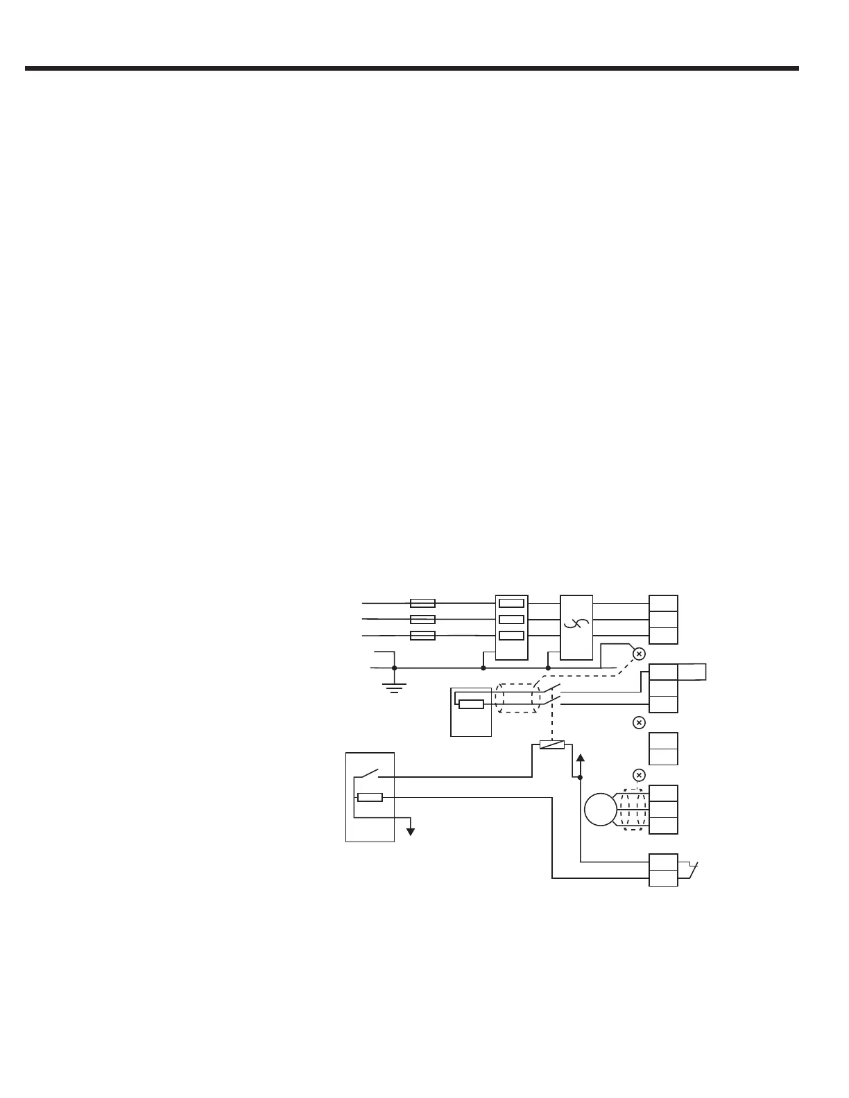
1.1.5. Monitor Circuit Wiring Diagrams
PT
F CH EMI
GND GND
L1
L2
L3
GND
GND
T1
T2
u
v
w
K1
K2
F5
X1A
GND
+ +
- -
PB
L1
L2
L3
BR
EC
Out DC
In BRT
M
VC
Brake Transistor
Watchdog
Com
DC
GND
+ PA
F Branch Circuit Fuses
CH Line Choke
EMI EMI Filter
BR Brake Resistor
DC DC Contactor
EC Elevator Control
VC Control Voltage
M Motor
PT Power Terminal
++ for housings E,G,H
+PA for housings R,U,W
Brake Transistor Monitor with Elevator Controller Supervision: DC Contactor

 Loading...


