Installation and Connection
• Plug in all connectors only in off-circuit condition !
• Observe correct phase sequence of the motor !
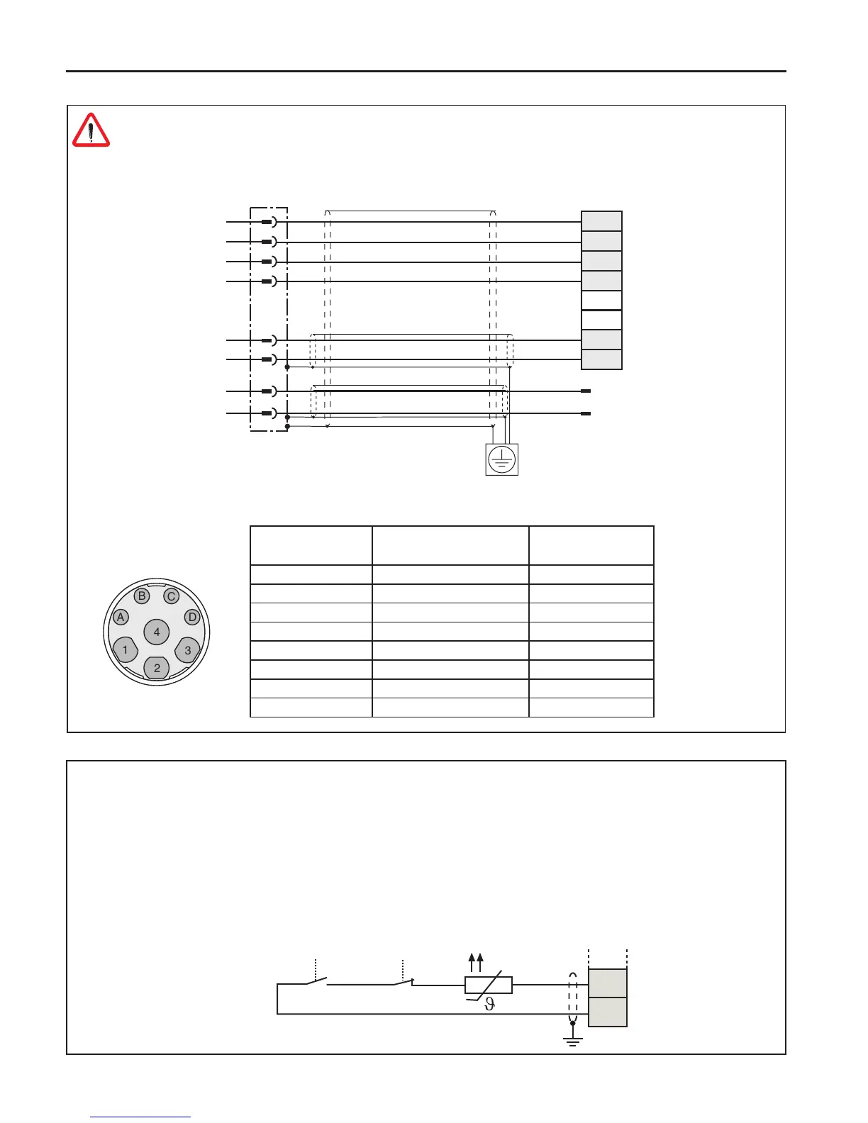
• Shielded motor line
PTC
PTC
Brake +
Brake –
Motor
Power connector
Motor-PTC
Other
• Terminals T1, T2
• Tripping resistance 1.65…4 kΩ
• Reset resistance 0.75…1.65 kΩ
• Design in accordance with VDE 0660 Part 302
• This function can be activated by the machine builder by software
• Do not lay connecting cable together with control cable
• Permissible in the motor cable only with double shielding
• Connect relay K1 for re prevention in regenerative operation (see 3.3.6)
Connector
PIN No.
Name
Cable
Core No.
1 U 1
4 V 2
3 W 3
2 green-yellow 4
A 5 5
B 6 6
C 7 7
D 8 8
 Loading...


