54
CONNECTION OF THE POWER UNIT
NOTICE
Minimum waiting time between two switch-on procedures 5 min-
utes !
5 min
on
off
Cyclicswitchingonandooftheunitleadstotemporaryhighresistance
of the resistor (PTC) in the input. A restart without limitation is possible
after cooling.
NOTICE
Destruction of the drive controller !
Never exchange connections mains input and motor output !
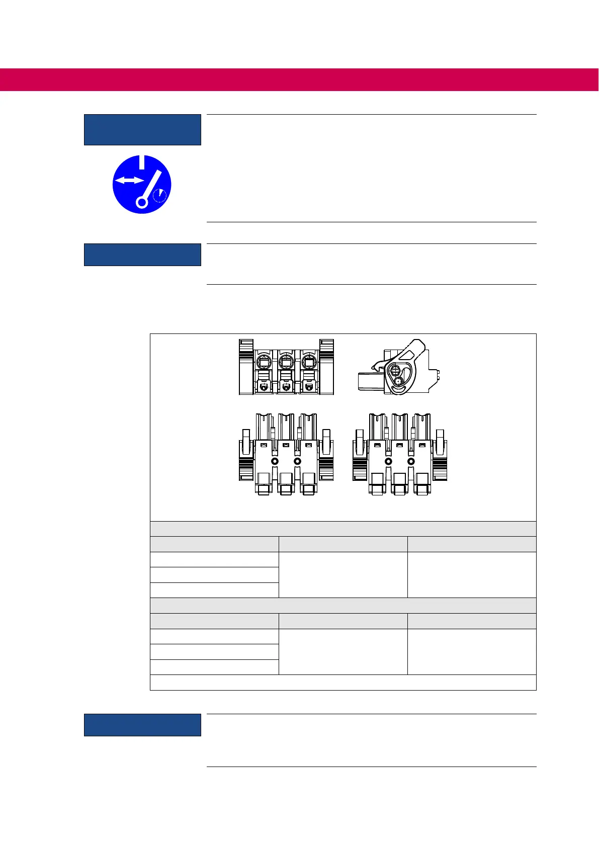
4.2.1.3 Mains terminal block X1A
L1 L2
L3
L1
N
400 V devices 230 V devices
400 V devices
Name Function Cross-section
L1
Mains connection
3-phase
0.5...2.5 mm²
AWG 20-14
L2
L3
230 V devices
Name Function Cross-section
L1
Mains connection
1-phase
0.5...2.5 mm²
AWG 20-14
L2
L3
Figure 14: Mains terminal block X1A
NOTICE
Pay attention to the connection cables !
In UL-relevant applications, only multi-wire cables (strands) are permit-
ted for devices of size 09 (1ph / 230V) at terminals X1A and X1B.

 Loading...


