69
BRAKE CONTROL AND TEMPERATURE DETECTION FOR P- CONTROL
4.4 Brake control and temperature detection for P- control
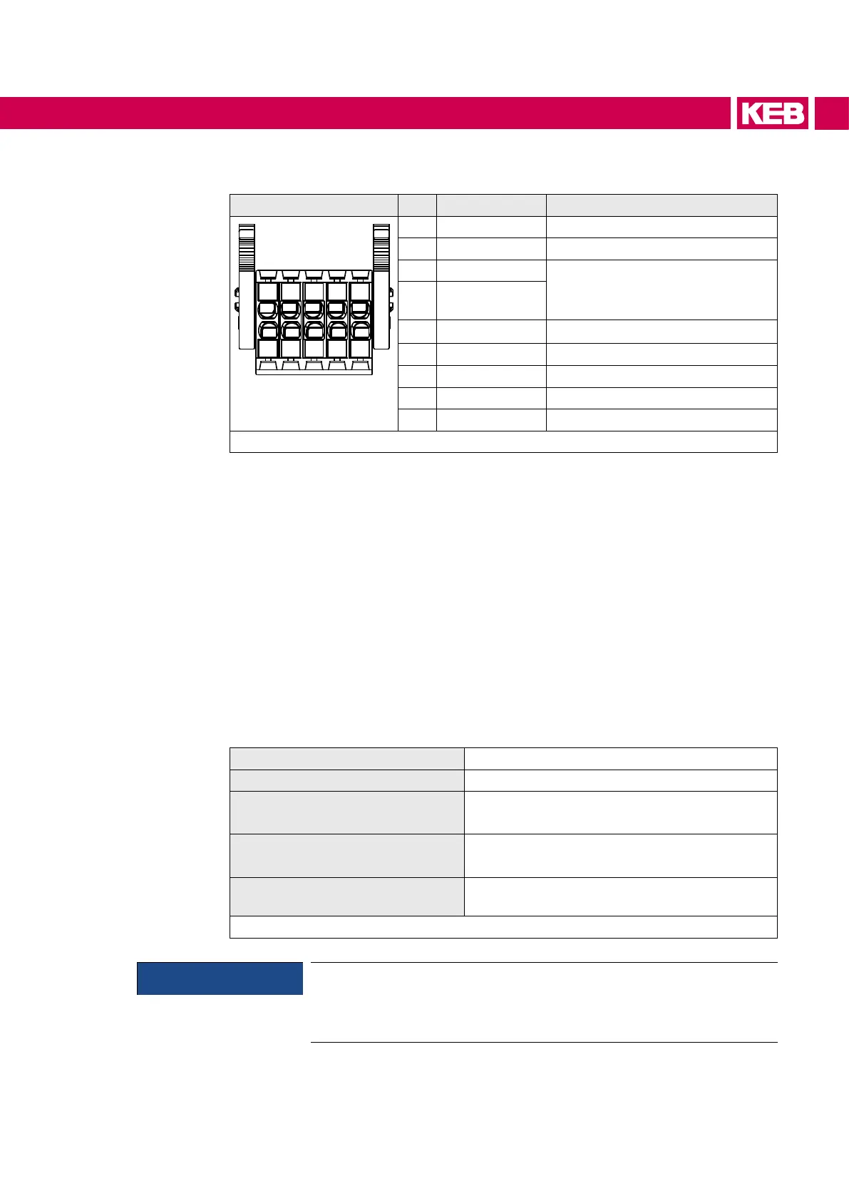
X1C PIN Name Notes
1
2
3
4
5
6
7
8
9
10
1 BR+ Brake control / output
2 BR- Brake control / output
3 0V for supply of the feedback inputs
P24Vin - 0.5 V / max. 1 A
(BR+ and 24Vout in addition 2 A)
4 24Vout
5 DIBR1 feedback input for brake control
6 DIBR2 feedback input for brake control
7 / 8 reserved
9 TA1 Temperature detection / input+
10 TA2 Temperature detection / input-
Figure 28: Assignment of the terminal block X1C for P-control
4.4.1 Specication and connection of the brake / relay control
Features of the control
• safely control one brake / relay
• control together two single brakes/relays; it must be the same brake/relay twice.
• Internal brake feedback without additional wiring or external via two digital brake
inputs.
• Power reduction through pulse width modulated control.
• Rapid demagnetization with a counter voltage of 27.5 V, maximum every 5s
• Current monitoring
The control, parameterization and reading of the feedback inputs of the brake is carried
out via the integrated safety module. Corresponding wiring and parameterization sug-
gestions are described in the safety manual type 5.
Name BR+ (X1C.1); BR- (X1C.2)
Function Output for control one/two brake(s) or relay(s)
DC output voltage
Minimum P24Vin -1,2 V
Maximum P24Vin
Maximum braking current
one brake: 2 A
two brakes: 2 x 1 A
Others
Internalfree-wheelingpath;internalltercir-
cuit;not short-circuit proof
Table 41: Specication of the brake control for P-control
NOTICE
Using a brake
► Choose the input voltage tolerance of the brake corresponding to the
tolerance of the output voltage.

 Loading...


