Do you have a question about the Keba KeContact KC-P30 e Series and is the answer not in the manual?
Explains hazard symbols and their meanings.
Describes the document's scope and purpose.
Lists required knowledge and abilities for electricians.
Specifies the intended purpose and limitations of the charging station.
Outlines conditions that void the warranty claim.
States the manual is part of the product and needs to be retained.
Lists the sections covered in the manual.
Lists topics not covered in this manual.
Provides website for additional manuals and information.
Warns about electrical hazards and proper installation by qualified personnel.
Details precautions against property damage from dampness, moisture, and improper handling.
Warns about risks of breaking the plastic housing due to improper mounting.
Lists essential components included in the delivery.
Details the specific parts for installation.
Lists components for wall mounting.
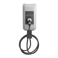
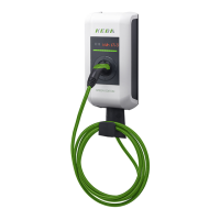
Identifies components visible on the front of the charging station.
Identifies components visible on the rear of the charging station.
Identifies components visible on the top of the charging station.
Explains the information found on the device's type plate.
Details different product types and their features based on designation.
Explains the functionality of different energy meter variants.
Describes certifications for vehicle compatibility.
Lists available options for the charging station.
Explains the function of the RFID reader for authorization.
Explains the function of the key switch for authorization.
Describes optional mobile network communication for charging networks.
Explains the function and segments of the LED status indicator.
Describes the optional dot matrix LED display for status information.
Warns about electrical hazards during mounting and the need for secure fixings.
Lists environmental and safety criteria for choosing an installation location.
Specifies necessary clearances for installation and adjacent units.
Lists the tools needed for the installation process.
Provides step-by-step instructions for physically mounting the charging station.
Details how to use the drilling template for marking holes.
Illustrates and labels all connection points on the charging station.
Warns about electrical hazards related to connections and the need for proper insulation.
Lists specific tools needed for electrical installation.
Details requirements for the power supply, including RCD selection.
Provides guidance on selecting the appropriate line circuit breaker.
Advises on sizing the power supply line, considering factors like temperature.
Explains correct methods for inserting cables into glands and seals.
Describes how to connect single-phase and three-phase voltage supplies.
Explains connections to different AC power supply systems like TN, TT, IT.
Explains the function of the enable input for controlling charging.
Details the states of the enable contact and the charging station.
Describes the switch contact output for status display or monitoring.
Shows the states of the switch contact for charging status.
Explains the use of the switch contact for monitoring contactors.
Shows the connection diagram for the switch contact output.
Explains the Ethernet connections for communication and diagnosis.
Warns about hazards related to shielding in Ethernet connections.
Provides the TIA-568A/B color coding for Ethernet wiring.
Explains how to configure the charging station using DIP switches.
Warns about possible damage to DIP switches if handled incorrectly.
Details DIP switches for control functions like enable input and switch contact.
Explains how to set the charging current using DIP switches.
Describes how to obtain an IP address automatically.
Explains how to manually set a fixed IP address for the station.
Details the DIP switch for activating network communication.
Explains the DIP switch for activating commissioning mode.
Provides instructions for inserting a SIM card for mobile network functions.
Provides instructions for removing a SIM card.
Explains how to enter and exit commissioning mode for inspections.
Step-by-step guide to activate commissioning mode.
Step-by-step guide to deactivate commissioning mode.
Outlines essential safety checks to be performed before operation.
Instructions for correctly installing all covers and applying seals.
Details how to attach seals to prevent tampering.
Step-by-step guide for replacing the fuse.
Explains the importance and process of software updates.
Instructions for replacing the SIM card.
Details how to change the cylinder lock for key switch versions.
Provides guidance on proper disposal of the charging station.
Provides general technical specifications of the charging station.
Lists power consumption and configurable current ratings for different series.
Details cable versions and socket variants.
Specifies operating and storage temperature ranges and other conditions.
Describes Ethernet, USB, enable input, and switch contact interfaces.
Lists available options like 4G/LTE communication.
Provides technical data for the calibratable energy meter.
Details MID accuracy classes and data recording for energy meters.
Provides physical dimensions and weight of the charging station.
Explains the structure of the product designation code.
| Charging Power | up to 22 kW |
|---|---|
| Protection Rating | IP54 |
| Operating Temperature | -25°C to +55°C |
| Rated Voltage | 400 V AC |
| Rated Current | 32 A |
| Output Current | 32 A |
| Cooling | Natural convection |
| Connection Type | Type 2 |
| Communication | OCPP 1.6 |
| Output Voltage | 400 V |