17
Installation and connection
ServoOne User Manual SERCOS II and III
ID no.: 1108.26B.3-00 Date: 04/2020
Installation and connection
4.2.4 Meaning of the LEDs
RJ-45 socket LEDs
There are two LEDs on each RJ-45 socket. These have the following signicance.
LED Meaning
1 (green) Link LED:
x Off: No link No connection to another bus user
x On: Link active There is a connection to another bus user
2 (orange) Activity LED:
x Off: No activity No data transfer
x Flashing: Activity Data transfer active
Table 4.2 Signicance of the LEDs on the RJ-45 socket
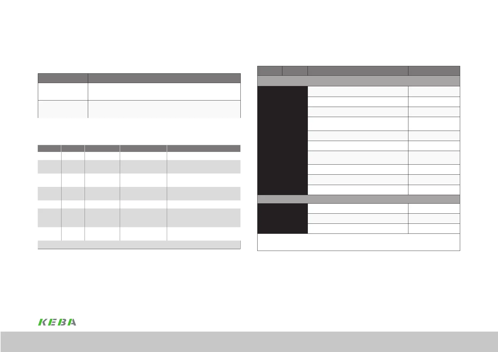
LED H1
Colour 1 Colour 2 State Description Comment
Green Green On CP4 no error
Green Off
Flashing with
4 Hz
Loopback
Change from fast forward to loopback
Red Green
Flashing with
4 Hz
Communication error
Dependent on S-0-1003 (ashes red
to green)
Red Red On
S III C1D
(Class 1 diagnostic).
See “Error messages in state class 1
(C1D)” on page 61
Orange Orange On CP0 . .CP3
Orange Off
Flashing with
4 Hz
Identication
(Bit 15 in the device controller) is used
for address assignment, conguration
errors or other identication purposes.
Off Off Off
No SERCOS III
communication
CPx: Communication phase
Table 4.3 Signicance of LED H1
4.3 Indication of the operating states via
7-segment display
D1 D2 Meaning Parameter
System states
8.
8.
Device in reset state
0.
Self-initialisation on device startup (Start)
S.*) 1.
1) Not ready to switch on (no DC link voltage) (NotReadyToSwitchOn)
S.*) 2.
1) Switch on disabled (DC link in order, power stage not
ready)
(SwitchOnDisabled)
3.
Ready to switch on (power stage ready) (ReadyToSwitchOn)
4.
Switched on (device is electrically live)
2)
(SwitchedOn)
5.
Drive ready (power applied to drive and drive ready for
reference value input)
2)
(OperationEnable)
6.
Quick stop
2)
(QuickStopActive)
7.
Fault reaction active
2)
(FaultReactionActive)
E R
Fault (see below) (Fault)
If there is a fault, the following is displayed alternately
E R.
Indication for fault or fault that cannot be acknowledged
X Y
Fault number (decimal)
X Y
Fault location (decimal)
1) S. flashes if the function STO (Safe Torque Off) is active, indication extinguishes if function is inactive.
*) This is not a "safe indication" in the context of EN 61800-5-2.
2) The dot ashes when the power stage is active.
Table 4.4 Operating states via 7-segment display
 Loading...

