40
Data transfer
ServoOne User Manual SERCOS II and III
ID no.: 1108.26B.3-00 Date: 04/2020
Data transfer
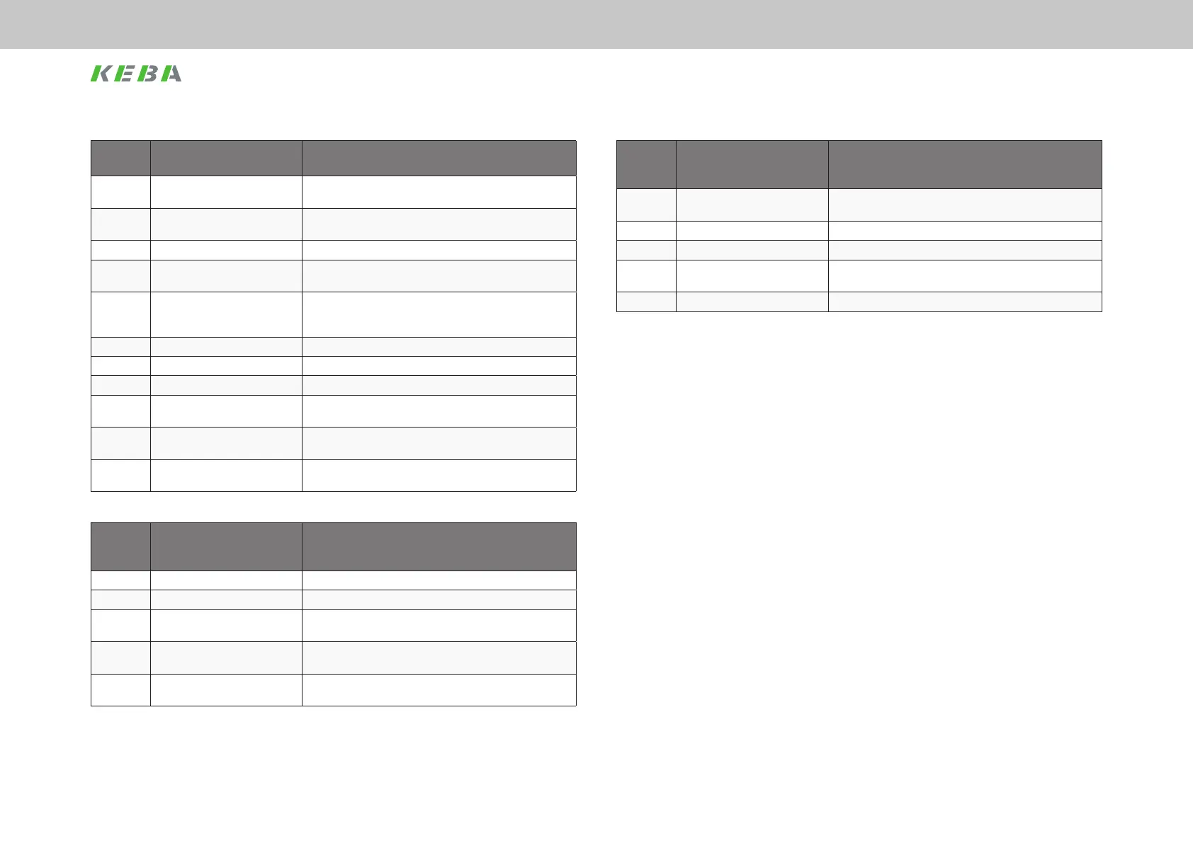
System
state
Designation Description
0 System initialisation in progress Initialisation after device reset (e. g. hardware, parameter list,
controller, …)
1 Not ready to switch on Initialisation completed, no mains or
DC link voltage lower than switch-on threshold
2 Start inhibit DC link voltage greater than switch-on threshold
3 Ready to switch on Power stage enabled via hardware (ENPO and ISDSH) and
bit 14 in the MDT
4 Switched on Power stage is enabled (bit 15 in the MDT = 1)
(State is passed through automatically during control via
SERCOS)
5 Control active Power supplied to motor, control active
5a Operation mode active The operation mode selected is active
5b Drive stop Drive stop active (standstill via stop ramp)
5c Command execution A command with movement sequence is active;
reference values from the SERCOS master are ignored
7 Fault reaction active Fault reaction is active, reference values from the SERCOS
master are ignored
8 Error Drive in fault state, reference values from the SERCOS master
are ignored, no drive torque
Table 7.4 Description of the system states
System
state
transition
Designation Description
0 START Initialisation after boot complete
1 UZK OK DC link voltage greater than switch-on threshold
2 ENABLE VOLTAGE Communication phase 4 active; ENPO input
=1 and bit 14 in the SERCOS control word = 1
3 ENABLE OPERATION Communication phase 4 active; bit 15 in the SERCOS control
word = 1
4 DISABLE OPERATION Communication phase 4 active; bit 15 in the SERCOS control
word = 0
Table 7.5 Description of the system state transitions
System
state
transition
Designation Description
5 DISABLE VOLTAGE Communication phase 4 active; ENPO input
=0 and/or bit 14 in the SERCOS control word = 0
6 UZK OFF DC link voltage lower than shut-off threshold
7 FAULT Fault event occurred (can occur in any system state)
8 FAULT REACTION ACTIVE The reaction congured in the parameters for the fault is active
(e.g. fault stop ramp)
9 FAULT RESET Fault reset using command S-0-0099
Table 7.5 Description of the system state transitions
7.3.6 Non-congurable real-time data
In addition to the mapped data, the MDT and the AT have xed congured content.
In the MDT this is:
y Device control: With the aid of this control word, the master controls
the topology of the slave or the ring. The control word is represented in
parameter S-0-1044.0.0, you will nd a detailed description in chapter
“10.2.1 Standard parameters” on page 64.
y Connection control: The connection control word contains, among other
items, the real-time control bits. For diagnostic purposes it is represented in
parameter S-0-1050.0.8 and S-0-1050.1.8, which are descried in more detail
in chapter “10.2.1 Standard parameters” on page 64.
The following data form a xed part of the AT:
y Device status: Here the slave signals its actual topology or the detection
of a break in the ring. This status word is represented in parameter "S-0-
1045.0.0" and is described in chapter “10.2.1 Standard parameters” on page
64.
y Connection status: Contains, among other items, the real-time status bits.
 Loading...

