37
Data transfer
ServoOne User Manual SERCOS II and III
ID no.: 1108.26B.3-00 Date: 04/2020
Data transfer
Bit 15 Bit 14 Bit 13 Bit 3
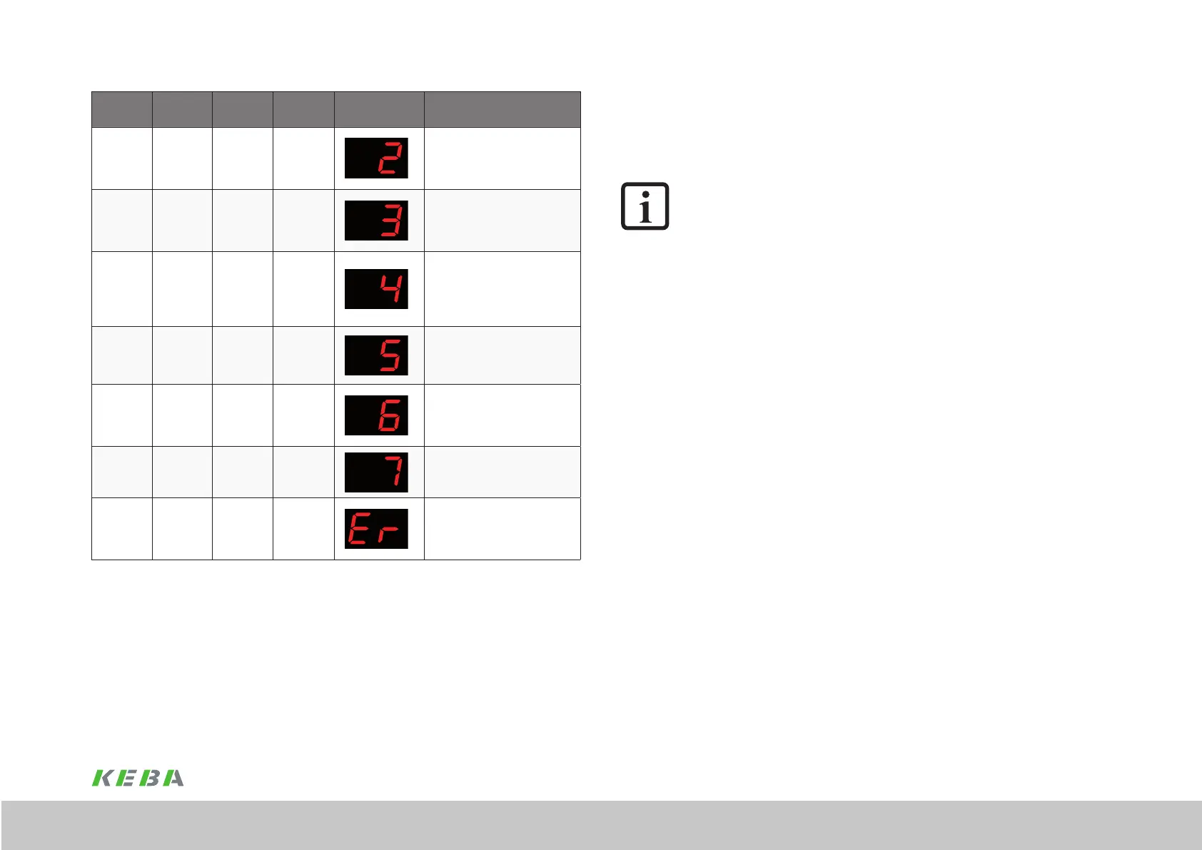
Display
System state designation
1 0 0 0
Start inhibit
Power stage not powered,
not enabled, no DC link
voltage
1 0 0 0
Ready to switch on
Power stage not powered,
enabled, DC link voltage
present
1 0 0 0
Switched on
Switch power stage to
active (activate the power
stage, motor commuta-
tion, brake management)
1 1 0 1 / 0
control active
Under control
(support for bit 3) drive follows the
reference values
1 1 0 0
Quick stop active
E.g. triggered via terminal,
drive no longer follows the
reference values
1 1 1 0
Fault reaction active
Drive no longer follows the
reference values
0 0 1 0
Error
Error number and error
location are indicated al-
ternately, no motor torque
Table 7.2 Representation on bits 3, 13, 14 and 15 of the system state
Bit 14: Drive ENABLE (power stage enable)
The ServoOne has a control input (X4.10) ENPO (Enable Power) for the hardware
enable on the control terminal. This input must be connected to 24V to operate the
power stage.
The device also has the "STO (Safe Torque Off)" function, category 3 (see Operation
Manual or Application Manual ServoOne) via the control input (X4.22) ISDSH. The logic
for this function (high edge on digital input ENPO (X4.10), where at the time of the edge
there must be a high signal on digital input ISDSH (X4.22), is to be provided by the
higher level controller as per the application manual.
NOTE:
If the ENPO and ISDSH inputs are not connected, the device remains in state
1 = "Not Ready to Switch On" or 2 = "Switch On Disabled". In the STO state,
the status indication ashes with "S1" or "S2".
Only after the correct conguration of ENPO (X4.10) and ISDSH (X4.22) can the
hardware be enabled using bit 14 in the drive control word. It is only possible to enable
the drive via bit 14 in communication phase 4.
Bit 15: Control ON/OFF (controller enable)
A few parameter settings must be made to control the drive via the SERCOS interface:
y Setting for controlling the drive via the SERCOS interface:
Congure P0159 to SERCOS III (9).
y Reference values via SERCOS prole:
Congure P0165 to SERCOS (8)
y Evaluation of bit 15 in the drive control word state-controlled (1 = LEVEL) or
edge-controlled (0 = EDGE) via P0144.
Comment:
If bit 14 and bit 15 in the drive control word are set at the same time,
congure P0144 as LEVEL (1).
So that the controller enable signal (bit 15) is accepted, i.e. the drive switches from the
unpowered state to the powered state, the following conditions must be met:
y SERCOS interface ready and in communication phase 4
y Power section enable via hardware (ENPO and ISDSH) and bit 14 in the drive
control word
y Drive not in error state
y Setting of the corresponding parameters P0144, P0159 and P0165
Under these preconditions, the drive indicates the drive state "3" on the display. The
drive is activated via the state change from 0 to 1 on bit 15 (controller enable) in the
drive control word. Once the enable has been undertaken successfully, the indication
 Loading...

