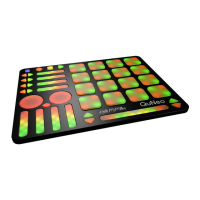
QuNeo hardWare
12
QuNeo
LED control will temporarily override the Remote LED Control for as long as the sensor is engaged.
The Sensors respond to incoming MIDI data in the following ways:
Pad LEDs
• In Drum Mode, pads will respond to MIDI notes sent on Channel 1* to engage the red and
green LEDs. A note sent with velocity greated than 0 will turn the LED on, and the velocity
of the note will determine the brightness. Refer to the MIDI Input diagram to look up which
MIDI Notes correspond to which pads.
• In Grid Mode, each corner of every pad can light up individually. The LEDs behave in 2
different ways, depending on which MIDI Channel the note message is sent on.
• Using MIDI Channel 2*, the corner of each pad receives a MIDI note for the green
LED and another MIDI note for the red LED. The velocity of the note determines the
brightness.
• Using MIDI Channel 3*, the corner of each pad receives one MIDI message to engage
the LEDs. The velocity of the note crossfades the LEDs from green to red.
*Note: These are the Default Channels for remotely controlling the LEDs, the channels can be changed in the Editor.
Horizontal and Vertical Slider LEDs - Each slider can receive a CC# value on Channel 1 for LED
location. The slider will ll in from the left (for Horizontal) or bottom (for Vertical). This works great for VU
metering! Refer to the MIDI Input diagram to look up which CC# corresponds to which slider.
Long Slider LEDs - LEDs will light up at a point determined by the value sent to CC# 5 on Channel 1.
Rotary LEDs - Each rotary can receive a CC# value on Channel 1 for LED location. The rotary LED will
light up in a clockwise motion starting at the bottom. Refer to the MIDI Input diagram to look up which
CC# corresponds to which rotary.
Transport Button LEDs - Each Transport button can receive a MIDI note on Channel 1 to control its LED.
A note sent with velocity greater than 0 will turn the LED on, and the velocity of the note will determine
the brightness. Refer to the MIDI Input diagram to look up which MIDI Note corresponds to which
button.
Up/Down and Left/Right Button LEDs - When Bank Switching is off, each arrow button will respond
to a MIDI note message. A note sent with velocity greated than 0 will turn the LED on, and the velocity
of the note will determine the brightness. Refer to the MIDI Input diagram to look up which MIDI Note
corresponds to which button.
Rhombus Button LEDs - When Bank Switching is off, the Rhombus button will respond to MIDI Note A1
to engage the green LED and MIDI Note G#1 to engage the red LED. A note sent with velocity greated
than 0 will turn the LED on, and the velocity of the note will determine the brightness.
NOTE: When Bank Switching is enabled, the Up/Down, Left/Right, and Rhombus button LEDs will NOT respond to
remote messages.
 Loading...