8
For resistance measurements (
Ω
2 and
Ω
4) greater than
100k
Ω
, more stable readings can be achieved by using
shielding. Place the resistance in a shielded enclosure
and connect the shield to INPUT LO. Shielded cable
should be used so the shield (INPUT LO) encircles the
other cable conductor(s).
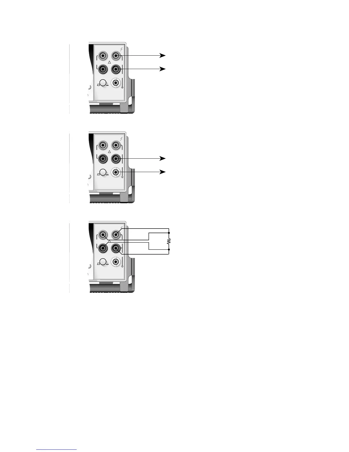
Figure 1. Basic measurement connections
2000 MULTIMETER
RANGE
!
F
500V
PEAK
FRONT/REAR
2A 250V
AMPS
HI
INPUT
LO
SENSE
Ω 4 WIRE
INPUTS
350V
PEAK
1100V
PEAK
AUTO
RANGE
R
Model 2010
Measure DCV, ACV,
Ω2, FREQ (PERIOD)
or TC TEMP *
* Thermocouple (TC) Temperature
measurements are typically
performed through a thermocouple
scanner card, such as the Model 2001-
TCSCAN. See the User's Manual for details.
2000 MULTIMETER
RANGE
!
F
500V
PEAK
FRONT/REAR
2A 250V
AMPS
HI
INPUT
LO
SENSE
Ω 4 WIRE
INPUTS
350V
PEAK
1100V
PEAK
AUTO
RANGE
R
Model 2010
Measure
DCI or ACI
2000 MULTIMETER
RANGE
!
F
500V
PEAK
FRONT/REAR
2A 250V
AMPS
HI
INPUT
LO
SENSE
Ω 4 WIRE
INPUTS
350V
PEAK
1100V
PEAK
AUTO
RANGE
R
Model 2010
Measure
Ω4 or RTD TEMP
R

 Loading...


