2-2 Connections Model 6485 and 6487 User’s Manual
Connection fundamentals
The following provides important fundamental information on input connections to the
Models 6485 and 6487. Typical connection drawings are provided in “Basic connections
to DUT,” page 2-5. More detailed connections for specific
measurements are in Section 3.
Model 6485 connections
Input connector
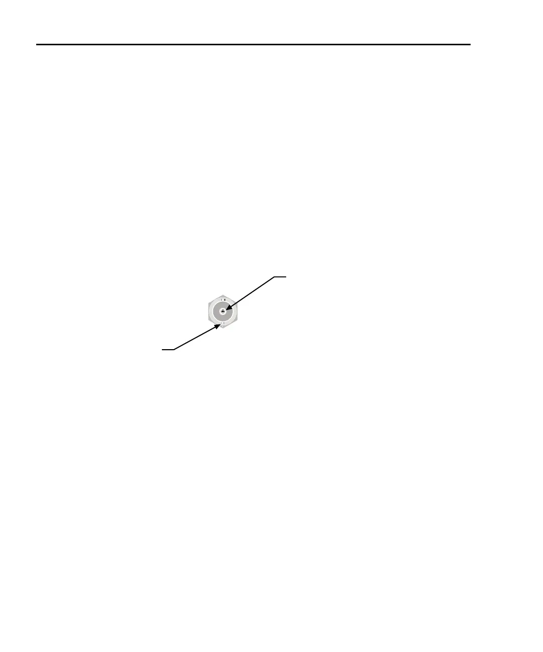
The rear panel INPUT connector is a 2-lug female BNC connector (Figure 2-1). Make
connections using a male terminated BNC cable (“Low noise input cables,” page 2-3).
Figure 2-1
Model 6485 BNC Input connector
Shield
(LO or GND)
Input
(Center Conductor)
CAT I
INPUT
Maximum input levels
The maximum input levels to the Model 6485 are summarized in Figure 2-2.
WARNING The
maximum safe voltage between picoammeter LO and chassis
ground (common mode voltage) is 42V. The Model 6485 does not
internally limit the LO-to-chassis voltage. Exceeding 42V can create a
shock hazard.
CAUTION The LO-to-chassis
breakdown voltage is 500V. Exceeding this voltage
may cause damage to the instrument.
Connecting COMMON or ANALOG OUTPUT to earth while floating
the input may da
mage the instrument.
NOTE Anal
og outputs will be at same voltages as applied to the BNC shell.